© Zennio Avance y Tecnología S.L. Edition 4 Further information
Page.
1
/
2
MINiBOX 25
Multifunction actuator with 2 outputs (16A) and 5 analog/digital inputs
ZIO-MN25
Technical Documentation
FEATURES
2 outputs configurable as:
1 shutter channel.
2 individual outputs*.
*
Suitable for capacitive loads, maximum 140 µF.
5 analog/digital inputs.
Manual output operation with push button and LED
status indicator.
Logical functions included.
Output timing facilities.
Total data saving on power failure.
Size 67 x 90 x 35 mm (2 DIN units).
Integrated KNX BCU.
DIN rail mounting (EN 50022), through pressure.
Possibility to connect different phases in adjoining outputs.
Conformity with the CE directives (CE-mark on the right side).
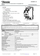
Programming/test button
: short press to set programming mode. If this button is held while plugging the device into the KNX bus, it enters the safe
mode.
If this button is held for more than 3 seconds, the device enters the test mode.
Programming/Test LED:
programming mode indicator (red). When the device enters into safe mode, it blinks (red) every half second. The manual
mode is indicated by the green color. During the start-up (reset or after KNX bus failure) and if the device is not in safe mode, it starts a blue blinking
sequence.
1
. Output status LED indicator
2
. Output control button
3
. Analog/Digital inputs
4
. KNX connector
5
. Programming/Test LED
6
. Programming/Test button
7
. Outputs
Figure 1.
MINiBOX 25
GENERAL SYSTEM SPECIFICATIONS
CONCEPT
DESCRIPTION
Type of device
Electric operation control device
KNX
supply
Voltage (typical)
29VDC SELV
Voltage range
21…31VDC
Maximum
consumption
Voltage
mA
mW
29VDC (typical)
7.5
217.5
24VDC
(1)
10
240
Bus connection
Typical TP1 bus connector for rigid cable 0.80mm Ø
External power supply
No
Operation temperature
from 0ºC to +55ºC
Storage temperature
from -20ºC to +55ºC
Operation humidity
5 to 95% RH (no condensation)
Storage humidity
5 to 95% RH (no condensation)
Complementary characteristics
Class B
Protection class
II
Operation type
Continuous operation
Device action type
Type 1
Electrical stress period
Long
Degree of protection
IP20, clean environment
Installation
Independent device to be mounted inside electrical panels with DIN rail (EN 50022)
Response on KNX bus failure
Data saving and relays action according to parameterization.
Response on KNX bus restart
Data recovering and output status change according to parameterization.
Operation indication
Programming LED indicates programming mode (red) and test mode (green). Output
status LED indicators reflect current output state.
Weight
117.5g
PCB CTI index
175V
Housing material
PC FR V0 halogen free
(1)
Maximum consumption in the worst case scenario (KNX Fan-In model)
1
2
3
4
5
6
7


