


ZENN
iO
AVANCE Y TECNOLOGÍA
vwww.zennio.com
11
11
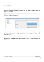
To have any of these letters or numbers shown in the navigation scheme of the header, it is
necessary that its referenced page has been previously
enabled
in ETS (see section 3.3).
Note:
Take into account that Page 1 is always enabled by default and that this cannot be
modified, so number 1 will always appear here.
Thanks to the navigation scheme, it is possible to identify the
current working page
, since
the corresponding letter or number is highlighted.
Moreover, it is possible to know the
security level
required to access every enabled page.
Symbol ( ) indicates that the corresponding page has a security level of
“1”, whereas symbol
(
) indicates level
“2” of security. See section 3.3.3 for further information about security in
pages.
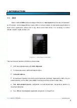
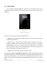
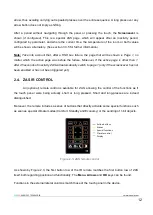
Buttons
The rest of the elements shown in the Display represent an outline of the 8 buttons of the
touch panel.
Since each of them will have an associated
text
(configurable by parameter) the functionality
of every enabled button can be intuitively identified.
Moreover, to identify which button has been pressed, the corresponding
icon
will be drawn
with the colour inverted (for example, in Figure 2.2, the button that is being pressed is the
second one from the right column).
Navigation
through the enabled pages is performed by short-pressing the Menu button and/or the
Arrow buttons of the touch panel (only if the option "Page Navigation" has been enabled, for every
button, through the corresponding ETS parameter. See section 3.3). A short press on the Menu
button will scroll through the enabled pages, in this order: 1
2
3
4
Configuration
Security
Indicators
1
2
…
A long press on this button will jump to the indicators page (or to page 1, if the indicators page has
not been enabled), no matter which the current page is.
If
“Page navigation" is enabled for the Arrow buttons, a short press over the arrow in the right (“up”
arrow), will change to the page next to the current one (rightward), while a short press over the
arrow in the left (
“down” arrow), will change to the page next to the current one, leftward. Using
these buttons permits, for instance, changing from page 3 to page 2 by a single press of the
“up”


