Zennio ZCL-ZB4, User Manual
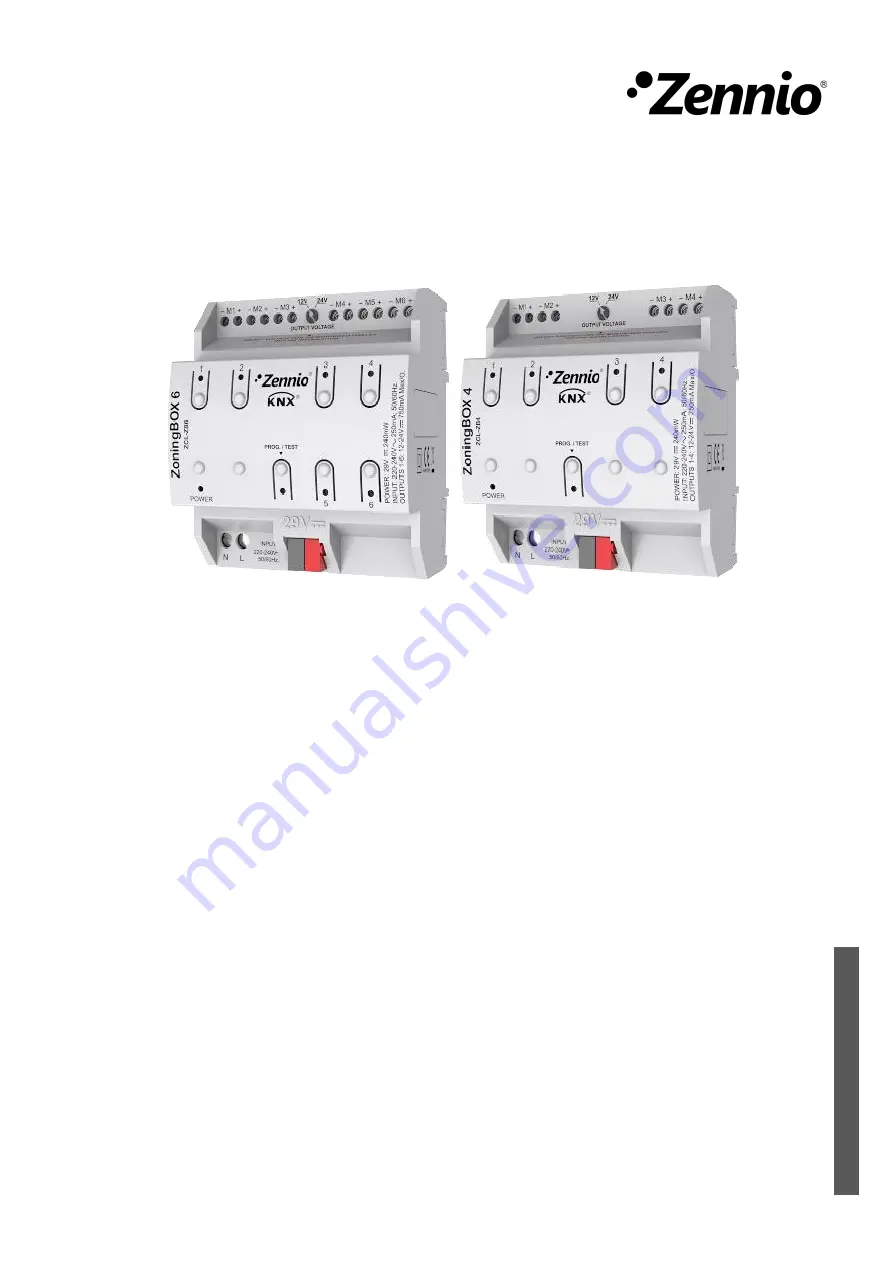
The Zennio ZCL-ZB4 is a smart 4-channel dimmer module that allows you to control the lighting in your home with ease. For detailed instructions on how to set up and use this product, download the User Manual for free from 88.208.23.73:8080. Get the most out of your ZCL-ZB4 with our comprehensive manual.
Share
Download


Reviews:
No comments
Related manuals for ZCL-ZB4

20
Brand: J4C Pages: 4

20
Brand: Vacon Pages: 62

ControlMaster CM15
Brand: ABB Pages: 28

650 series
Brand: ABB Pages: 128

ACS880 Series
Brand: ABB Pages: 50

ABILITY SSC600
Brand: ABB Pages: 42

AC 800M
Brand: ABB Pages: 120

ACH400 Series
Brand: ABB Pages: 28

TZIDC-110
Brand: ABB Pages: 59

ACS355 series
Brand: ABB Pages: 139

LME620-AI
Brand: ABB Pages: 15

PST30
Brand: ABB Pages: 10

LME620-AI
Brand: ABB Pages: 30

LME620-AI
Brand: ABB Pages: 44

XFC G5
Brand: ABB Pages: 2

ControlMaster CM15
Brand: ABB Pages: 4

Leroy-Somer R180
Brand: Nidec Pages: 20

5800 Series
Brand: S&C Pages: 34


