© Zennio Avance y Tecnología S.L.
Edition 3
Page.
1
/
2
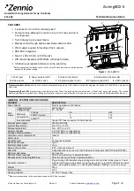
ZoningBOX 6
Ducted Air Zoning Actuator for up to 6 Zones
ZCL-ZB6
Technical Documentation
FEATURES
6 outputs for 12 or 24V motorised grilles*.
Zoning module allowing the control of up to 12 zones and up to
2 zone groups.
Total data saving on power failure.
Manual control through buttons and status indicator LED.
230V supply required for feeding of the 6 outputs.
KNX BCU integrated.
Size 67 x 90 x 80 mm (4.5 DIN units).
DIN rail unit assembly (EN 50022), with snap fit clamp.
CE directives compliant (CE-mark on the right side).
* Before connecting the device to the facility, it must be assured that the switch position
agree with the grilles voltage.
Programming/test button
: short button press to set programming mode. If this button is held while plugging the device into the KNX bus, it goes into
safe mode.
Programming/Test LED:
programming mode indicator (red). When the device goes into safe mode, it blinks (red) every half second. The manual
mode is indicated by the green color. During start up (after reset or power failure) and if the device is not in safe mode, LEDs indicator blink red once.
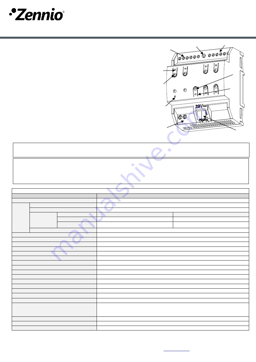
Figure 1.
ZoningBOX 6
3
4
6*
9
7
1
5
2
5
8
GENERAL SYSTEM SPECIFICATIONS
CONCEPT
DESCRIPTION
Type of device
Electric operation control device
KNX
supply
Voltage (typical)
29VDC SELV
Voltage range
21…31VDC
Maximum
consumption
Voltage
mA
mW
29VDC (typical)
6
174
24VDC
(1)
10
240
Bus connection
Typical TP1 bus connector; 0.80mm² section
External power supply
230VAC 50/60Hz
Ambient temperature
from 0ºC to +45ºC
Storage temperature
from -20ºC to +55ºC
Ambient humidity
5 to 95% RH (no condensation)
Storage humidity (relative)
5 to 95% RH (no condensation)
Complementary characteristics
Class B
Safety class
II
Operation type
Continuous operation
Device action type
Type 1
Electrical stress period
Long
Degree of protection
IP20, clean environment
Assembly
Independent device to be mounted inside electrical panels with DIN rail (EN 50022).
Minimum clearances
Not required
KNX bus failure response
Data saving according to parameterization
Response when restarting KNX bus
Data recovering according to parameterization
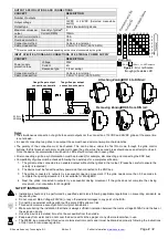
Operation indication
Programming LED indicates programming mode (red) and test mode (green). Power
indicator LED (green) represents correct feeding. Each output LED indicates its status
(fixed = open grille/dumper; off = closed grilled/dumper; flashing = error, see Fig. 2)
Weight
201g
PCB CTI index
175V
Housing material
PC FR V0 halogen free
(1)
Maximum consumption in the worst case scenario (KNX Fan-In model)
1
. 230V input
2
. Power indicator LED
3
. Grille control button
4
. Grille status indicator LED
5
. Grille outputs
6
. 12/24V switch
7
. Programming/test button
8
. Programming/test LED
9
. KNX connector


