© Zennio Avance y Tecnología S.L.
Ed. 3
Further info:
www.zennio.com
Page
4
/
8
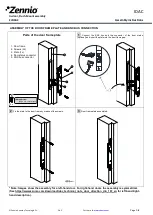
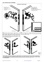
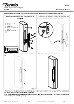
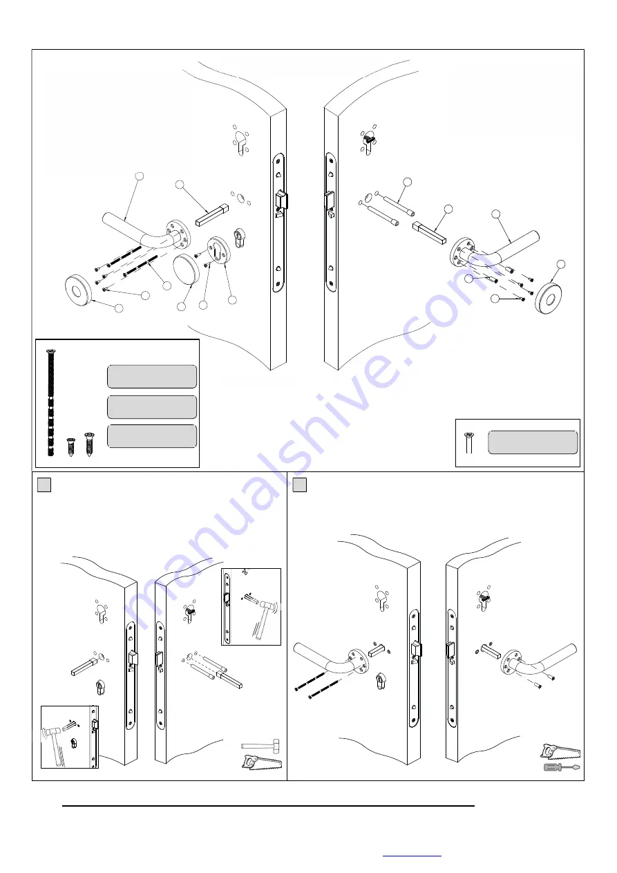
HANDLES ASSEMBLY
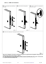
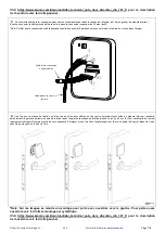
* Note: Images show the assembly for a left-hand door. For right-hand doors the assembly is symmetrical.
(See https://www.zennio.com/download/idac_technical_note_door_direction_din_107_en for left-hand/right-
hand description).
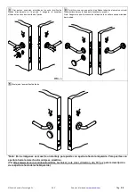
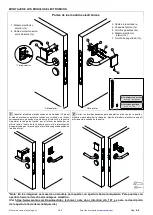
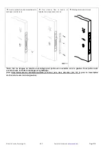
1
Insert the square spindles in both sides of the door, making
sure they enter as far as they will go into the lock hole (it might be
necessary to use a Nylon hammer or similar). Insert the screw
isolators in the holes (from the internal side of the door) and, if it is
necessary, cut the excess in order to adapt their length to the door
thickness. The isolators should be cut with a chisel.
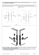
2
Once the screw isolators and square spindles are installed, fix the
handles with the through-screws and the threaded bushings. It may be
necessary to previously cut the through-screws to adapt their length to the
door thickness.
9
10
11
12
1
2
6
7
8
3
4
5
13
5
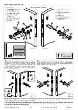
1. Handle (1x)
2. External square spindle with
isolator (1x)
3. Through-screws (2x)
4. Fixing screws (8x)
5. Handle base cover (1x)
6. Keyhole cap (1x)
7. Fixing screws (2x)
8. Keyhole (1x)
9. Screw isolators (2x)
10. Internal square spindle
with isolator (1x)
11. Handle (1x)
12. Threaded bushings (2x)
13. Handle base cover (1x)
* Internal view
* External view
Handle parts
(3)
(3) Threaded through-screw
M4 x 90 - countersunk
(4)
(4) Wood screw
Ø3.5 x 16 - countersunk
(7) Wood screw
Ø4 x 20 - countersunk
2x
8x
2x
(7)
(12) Threaded bushing
M4 x 16 - countersunk
(12)
2x


