© Zennio Avance y Tecnología S.L.
Ed. 3
Further info:
www.zennio.com
Page
7
/
8
3
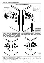
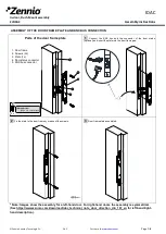
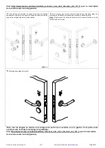
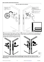
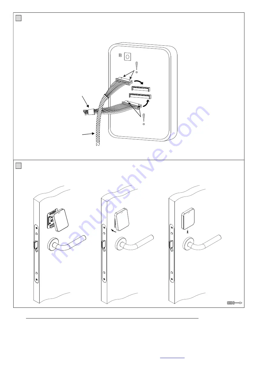
Connect into the 15-pin connector (bigger one) of the internal module the interconnection cable from the external module. Then, connect the
cable coming from the electric lock into the upper 12-pin connector (smaller one).
*Note: Verify that each cable is connected with the correct polarity (there must be 2 small notches in the upper part, like it is shown in the figure).
4
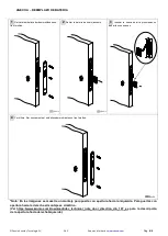
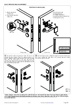
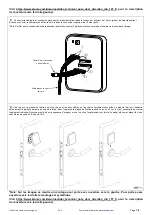
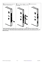
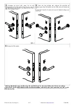
Once the fixing plate is tightened and both cables are connected to the internal module, insert softly the upper part of the internal module in the
upper tab of the fixing plate until it clicks (it is necessary to slightly rotate the device like shown in the image sequence). Then, when the upper part
is fitted, close the lower part and insert the security screw with a Torx screwdriver.
* Note: Images show the assembly for a left-hand door. For right-hand doors the assembly is symmetrical.
(See https://www.zennio.com/download/idac_technical_note_door_direction_din_107_en for left-hand/right-
hand description).
Module
interconnection cable
Cable coming from
the electric lock
①
②


