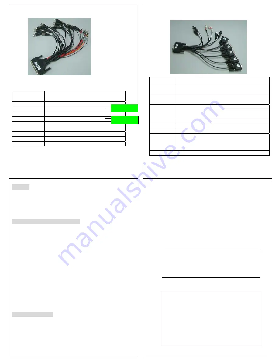
Input Bridal DB37 (Video/Audio IN/ Sensor Input)
Label
Description
V1/ V2/ V3/ V4
Video input for camera number 1/2/3/4
V5 / V6 / V7/ V8
Video input for camera number 5/6/7/8
A 1/ A 2/ A 3/ A 4
Audio input for camera number 1/2/3/4
A5 /A6 / A7 /A8
Audio input for camera number 5/6/7/8
Color coded wire
Description
Sen 1-8 (Red)
Sensor 1-8 (0~36 V) input
A/D –IN2(Green)
Enable the Analog to Digital input
Sensor-INV Connect
with Speed Sensor
4
Only for 8ch
Only for 8ch
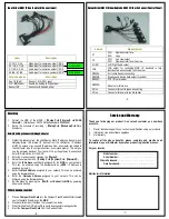
Output Bridal DB25 (Video/AudioOut/RS232/Inertia Sensor/Control Panel)
Label
Description
V1
4CH Operation Interface
8CH Logo
V2
4CH Live view output
8CH Operation Interface /Live view
AL/ AR
Left/ Right Audio output
VGA
VGA output for controlling MDR. IR handheld is fully
functional when connected to VGA output
RS232A
For Inertia Sensor connecting
RS232B
Steering and device data output (hyperlink)
RS232C
PTZ / ID card reader
RS232D
Reserve for future use
4 Pins
Connector for control panel connecting
2 Pins
Connector for power to Inertia sensor
-5-
Recording
1.
Format the HDD of the MDVR. (
Ǐ
Setup
ǐ
Î
Ǐ
System
ǐ
Î
Ǐ
HDD
Format
ǐ
). (Default user: 00000. Default password: 88888888)
2.
Setup the schedule of recording. (
Ǐ
Setup
ǐ
Î
Ǐ
Schedule
ǐ
Î
Date,
Schedule)
Network Settings Connected through a Router
1.
Gather the following from the LAN/Router: Static IP address, Subnet mask,
Gateway.(Note: The internal IP derives from the LAN/router. IP address
MUST be unique or an unused IP address. From a computer connected to
the LAN/router type IP configuration from a command prompt. This will give
you the gateway & subnet from the LAN. Copy the gateway & subnet and
enter this information into the DVR
2.
Enter the menu screen by pressing the
Ǐ
Setup
ǐ
.
3.
Setup the network details. (
Ǐ
Setup
ǐ
Î
Ǐ
System
ǐ
Î
Ǐ
Network
ǐ
)
4.
Enter the IP Address specifically assigned for the MDR on your network.
This can be achieved using the Arrow buttons. (NOTE: IP Address is
assigned by router)
5.
Enter the Mask Address assigned to your network. This can be achieved
using the Arrow buttons
6.
Enter the Gateway Address assigned to your network. This can be
achieved using the Arrow buttons.
7.
Exit the Menu by pressing the
Ǐ
Exit
ǐ
and Reboot the MDR by powering
it down and back up.
CF Card backup recorder
1.
Place a Compact Flash Card into the Compact Flash Reader/Writer located
next to the Hard Drive Bay on the MDR.
2.
Playback (full screen) the video that you want to archive.
3.
When finished the DVR will notify you with a successful message button.
4.
Eject the Compact Flash Card from the Reader/Writer.
-6-
Service and Warranty
Thank you for buying our product. As a valued customer, you now have
access to :
1.
Prompt technical support if you confront any difficulties using our products
2.
Information, tips and software upgrades
3.
Our warranty
To realize all the above benefits, please complete and provide some
information to your distributor by email as product registration process.
For your records
Distributor information
-7-
Model number: ……………………………………………
Serial Number: ………………………….........................
Where Purchased: …………………………………………….
Date Purchased: ………
……………
.....................


