background image

8

Typhoon, Hurricane, & Cyclone Guide d’utilisation, d’entretien et d’installation

S O U S - A R M O I R E

T Y P H O O N ,   H U R R I C A N E 

&   C Y C LO N E

C O R E

Instructions d’installation 

Total

     =

3- 1/ 4” x 10”

1 pi            x (      )   =

pi   


5 pi            x (      )   =

pi  


20 pi          x (      )   =

pi  


6”, 7”, 8”, 10”  15 pi 


x (      )   =

pi   

6”, 7”, 8”, 10”


9 pi            x (      )   =

pi   

pi   

6”, 7”, 8”, 10”  1 pi            x (      )   =

pi    

Total

     =

6”, 7”, 8”, 10” 30 pi          x (      )   =

pi   


pi   

pi   

pi   

6”, 7”, 8”, 10” 30 pi          x (      )   =

pi  


1 pi            x (      )   =

pi  


16 pi          x (      )   =

pi  


8 pi            x (      )   =

pi  


23 pi          x (      )   =

pi  


7” to 6” or
8” to 7” circ. 
reducteur
conique

25  pi 

x (      )   =

pi   

3- 1/ 4” x 10”

15 pi          x (      )   =

pi 

3- 1/ 4” x 10”

9 pi            x (      )   =

pi   

3- 1/ 4” x 10”

24 pi          x (      )   =

pi 


30 pi          x (      )   =

pi 


 pi          x (      )   =

pi 


15

6”, 7“, 8”
circ. 
bouchone de
l’air

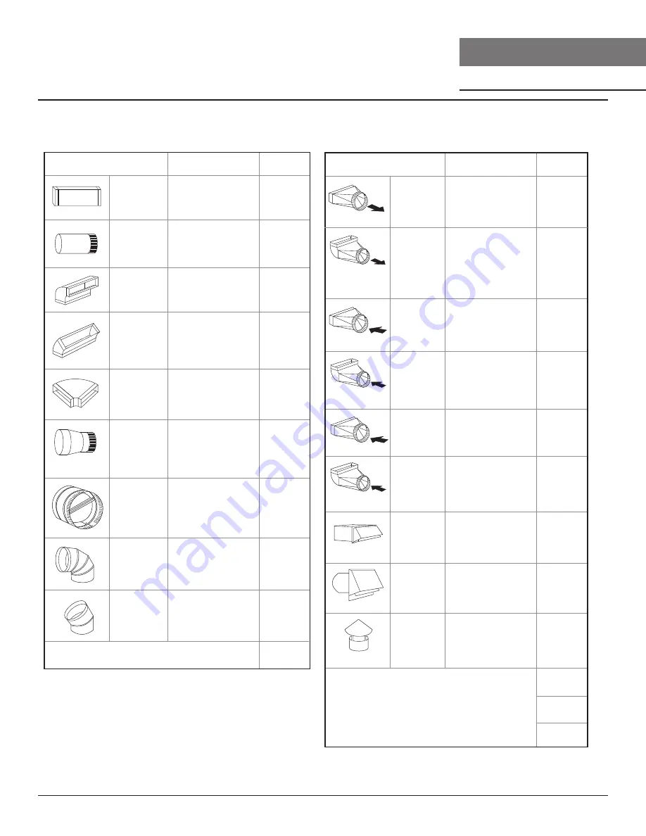
Pièces de conduit

Longueur x 
Nombre utilisé  

rect., droit

circ., droit

rect.,
coude à 90º 

rect.,
coude à 45º 

rect.,
coude plat
à 90º

circ.,

coude à 90º

coude à 45º

Sous-total - colonne 1=

Longueur maximale du conduit d’aération : 

Pour un mouvement d’air convenable, la longueur totale d’un conduit
d’aération ne devrait pas compter plus que l’équivalent de 150 pieds.

Pièces de conduit

Longueur x 
Nombre utilisé  

6” circ. à
rect. de
3-1/4" x 10",
coude à 90º

6” circ. à
rect. de
3-1/4" x 10" 

6” circ. à
rect. de
3-1/4" x 10" 

6” circ. à
rect. de
3-1/4" x 10",
coude à 90º

7” circ. à
rect. de
3-1/4" x 10" 

7” circ. à
rect. de
3-1/4" x 10",
coude à 90º

3-1/ 4” x 10”

embout mural
rect./registre

embout
mural
circ./registre

chapeau de
toiture circ.

Sous-total - colonne 2    =

Sous-total - colonne 1    = 

Total du conduit  =

Feuille de calcul pour le conduit d’aération

Summary of Contents for Cyclone AK6500B

Page 1: ...S B W AK2142CS AK2148CS EN Use Care and Installation Guide FR Guide d utilisation d entretien et d installation Hurricane AK2500CS B W AK2536CS B W Cyclone AK6500CS B BS W AK6536CS B BS W AK6542CS Airflow Control Technology TM C C Airflow Control Technology TM C C ...

Page 2: ...2 Typhoon Hurricane Cyclone Use Care and Installation Guide T YPHOON HURRICANE CYCLONE UNDER CABINET CORE ...

Page 3: ...12 AK25 Hood Specifications 13 AK65 Hood Specifications 14 Electrical Supply 15 Cable Lock 15 Rectangular Vertical Ducting Preparation 16 Rectangular Horizontal Ducting Preparation 17 18 Mounting the Hood 19 20 Features Controls 21 23 AK21 Capacitive Touch 21 AK25 Electronic Touch 22 AK65 Mechanical Slide 23 Maintenance 24 27 Hood Filter Cleaning 24 26 LumiLight LED 27 ACT Conversion 28 30 Airflow Co...

Page 4: ...ecting means cannot be locked securely fasten a prominent warning device such as a tag to the service panel General Safety WARNING Warning means that failure to heed this safety statement may result in extensive product damage serious personal injury or death CAUTION Caution means that failure to heed this safety statement may result in minor or moderate personal injury property or equipment damag...

Page 5: ...paces within walls ceilings attics crawl spaces or garages WARNING WARNING TO REDUCE THE RISK OF FIRE ELECTRIC SHOCK OR INJURY TO PERSONS OBSERVE THE FOLLOWING a Installation work and electrical wiring must be done by qualified person s in accordance with all applicable codes and standards including fire rated construction b Sufficient air is needed for proper combustion and exhausting of gases thro...

Page 6: ...n conformance with National Electrical Code ANSI NFPA 70 latest edition or CSA standards C22 1 94 Canadian Electrical Code Part 1 and C22 2 No 0 M91 latest edition and all local codes and ordinances Ź If codes permit and a separate ground wire is used it is recommended that a qualified electrician determine that the ground path is adequate Ź Do not ground to a gas pipe Ź Check with a qualified elect...

Page 7: ...ition adapter AK21 AK25 6 Round transition adapter AK65 pre installed on top of hood 3 1 4 x10 rectangular cover plate pre installed on back of hood 3 1 4 x10 rectangular vertical transition adapter 3 1 4 x10 rectangular starting collar Washer 4 Parts Not Supplied Ducting conduit and all installation tools Backdraft damper Philips head screwdriver with minimum 8 long shaft required to install AK21...

Page 8: ...h damper 30 Ft x Ft Ft Ft Ft 6 7 8 10 Round roof cap 30 Ft x Ft Subtotal column2 Subtotal column1 Total ductwork Maximum Duct Length For satisfactory air movement the totalductlengthshould not exceed 150 equivalent feet 6 roundto 3 1 4 x 10 rect transition 1 Ft x Ft 6 roundto 3 1 4 x 10 rect transition 900 elbow 16 Ft x Ft 7 roundto 3 1 4 x 10 rect transition 8 Ft x Ft 7 roundto 3 1 4 x 10 rect tr...

Page 9: ...9 Typhoon Hurricane Cyclone Use Care and Installation Guide ZEPHYRONLINE COM Installation Instructions Mounting Height Clearance Ducting 36 24 min 32 max ...

Page 10: ...n the two transitions as possible Minimum mount height between range top to hood bottom should be no less than 24 Maximum mount height should be no higher than 32 It is important to install the hood at the proper mounting height Hoods mounted too low could result in heat damage and fire hazard while hoods mounted too high will be hard to reach and will loose performance and efficiency If available ...

Page 11: ...l joints w certified Silver Tape or Duct Tape Fire Hazard NEVER exhaust air or terminate ductwork into spaces between walls crawl spaces ceilings attics or garages All exhaust must be ducted to the outside unless using the recirculating option WARNING side wall cap w gravity damper cabinet cabinet soffit or crawl space side wall cap w gravity damper 3 1 4 x10 rear ducting w side wall gravity damper...

Page 12: ...16 1 7 16 9 15 16 30 28 1 16 36 34 42 39 3 4 48 45 3 4 5 1 16 2 3 4 8 5 8 30 11 5 16 36 12 1 2 42 12 1 2 48 12 1 2 1 15 16 elec k o 30 29 3 4 36 35 3 4 42 41 3 4 48 47 11 16 30 14 36 17 42 19 7 8 48 22 7 8 C L 13 9 16 20 3 4 7 7 8 1 3 8 9 15 16 2 1 2 30 11 5 16 36 12 1 2 42 12 1 2 48 12 1 2 C L 3 1 16 6 7 8 6 7 8 elec k o TOP SIDE FRONT BACK ...

Page 13: ... Installation Guide ZEPHYRONLINE COM Installation Instructions śŞ Ů 30 29 3 4 36 35 3 4 14 5 8 7 1 8 1 7 8 11 1 4 3 3 4 11 7 8 C L 3 3 4 6 7 8 elec k o TOP SIDE FRONT BACK 8 5 8 1 1 8 Ø 6 7 8 30 27 7 8 36 33 7 8 C L 11 7 8 2 5 1 4 22 1 8 2 1 8 ...

Page 14: ...UNDER CABINET CORE Installation Instructions şŞ Ů 3 1 16 1 7 16 9 15 16 30 27 7 8 36 33 7 8 42 39 7 8 4 1 2 1 3 16 8 5 8 11 7 8 2 elec k o 30 29 3 4 36 35 3 4 42 41 3 4 30 14 36 17 42 20 C L 15 3 8 22 1 4 6 5 16 1 3 16 9 15 16 2 1 16 C L 3 1 16 6 6 elec k o TOP SIDE FRONT BACK 11 7 8 5 1 2 ...

Page 15: ...e extension cord or adapter plug with this appliance Follow national electrical codes or prevailing local codes and ordinances This appliance requires a 120V 60Hz electrical supply and connected to an individual properly grounded branch circuit protected by a 15 or 20 ampere circuit breaker or time delay fuse Wiring must be 2 wire w ground Please also refer Electrical Diagram labeled on product Ca...

Page 16: ...t the Cyclone is pre configured for 6 round vertical ducting 1 Using a Philips head screwdriver remove the screws and round vertical transition adapter from top of hood body 2 Replace round vertical transition adapter with rectangular transition adapter Do not secure to hood body yet 3 Place 3 1 4 x10 rectangular collar on top of rectangular transition adapter Secure rectangular adapter and rectang...

Page 17: ... Cyclone is pre configured for 6 round vertical ducting 1 Using a Philips head screwdriver remove the screws and round vertical transition adapter from the top of the hood 3 Typhoon ONLY Remove the two plastic air diverter blocks The blocks are located in the hood and can be accessed from the top when the round transition adapter is removed 2 Using a Philips head screwdriver remove the screws and 3...

Page 18: ...transition adapter Do not secure to hood body yet 6 Place 3 1 4 x10 rectangular collar on back of hood and secure using the screws that previously secured the rectangular cover plate 5 Place 3 1 4 x10 rectangular cover plate over the rectangular opening on top of hood from step 4 Secure rectangular transition adapter and cover plate to hood body using the previously removed screws from step 1 ...

Page 19: ...and Installation Guide ZEPHYRONLINE COM Installation Instructions Mounting the Hood bottom panel lighting harness wood blocking installation screws and key holes duct work residue cups safety grilles electrical duct tape LumiLight LED FIG B ...

Page 20: ...removing bottom panel Take care not to scratch side panels during removal 5 Install 4 wood screws to cabinet bottom by following the installation screw hole dimensions on Page 12 14 These screws will be used to secure the hood to the cabinet 6 Lift hood onto screws located on cabinet bottom and lock into place Make sure all 4 key holes cover the screws Tighten each screw to secure hood to cabinet ...

Page 21: ...s Ě Ű Ĭ ĭĘ Ě Ű Ę Ĭ ė Ű Ŝ Ę Ŝ Ęĭ Ű Ě ĕ Ę Ş Ű Ę Ě Ş ŰĘ Ě Ű Ű Ű Ę Ů Ě ů Ĭ ĭ Ę Ě ė Ě Űĕ Ů Ę Ɔ Ę ĕ ś ć Ŝ Ɔ ŜŢř Ę ć ś Ɔ śŢř Ę Q 2 3 1 ħ Ű 4 ė ĕ ĕ Ş Ŝ 1 ħ Ű ś Ě Ę şĕ Şĕ ŝĕ Ŝĕ śĕ Ĭ ĭĘ Ě Űĕ Ű Ę Ŝ Ě Ę ĕ Ĭ ĭĕ śĕ Ŝĕ ŝĕ Şĕ ş Ě Űĕ Ű Ę 4 Ě ĕ ĕ Ę Ě Űĕ ĕ ĕ Ę Ş Ě Ę Ĭ ĭĕ śĕ Ŝĕ ŝĕ Ş şĘ 4 5 6 ś AK21 Capacitive Touch ...

Page 22: ...e T YPHOON HURRICANE CYCLONE UNDER CABINET CORE Features Controls 1 ħ Ű Ě Ű Ĭ Ęĭ Ě Ű Ę Ĭ ė Ű Ŝ Ę Ŝ Ęĭ Ű Ě ĕ Ę Śĕ Ű Ş Ű Ę Ě Ű Ű Ű Ę Ů Ě ů Ĭ ĭ Ę Ě ė Ě Űĕ Ů Ę Ɔ Ę Ś ś Ɔ ŜŢř Ę Ś Ɔ śŢř Ę ś Ě ĕ Ę Ě Űĕ Ę Ę ŰĘ Ŝ Ě Ę Ś ĕ ś ĕ Ŝ Ę 1 2 3 1 ħ Ű ś ħ Ű Ŝ AK25 Electronic Touch ...

Page 23: ...lower On Off Speed Selection 1 Lights Off Dim Bright 2 BLOWER ON OFF SPEED SELECTION 0 is off 1 is low speed 2 is medium speed and 3 is high speed LIGHTS OFF DIM BRIGHT 0 is off 1 is dim and 2 is bright 1 2 1 2 0 3 1 0 2 2 ACT Airflow Control Technology is not available on AK65 AK65 Mechanical Slide ...

Page 24: ...nal housing All hoods are equipped with dishwasher safe residue cups to collect cooking residue during the self cleaning function Cooking residues are often automatically liquefied and can accumulate in the residue cups from everyday use Nevertheless grease from cooking could also dry and adhere to the internal housing Running the self clean function periodically will flush out accumulated residue i...

Page 25: ...ning Instructions 1 Power on blowers at Speed 1 2 With nozzle on spray squirt grease cutting detergent onto blower wheel blades 30 35 times Repeat for each blower Leave blower on for 10 minutes Detergent will collect in the residue cups 3 Remove residue cups Clean residue cups and in dishwasher or clean by hand Install residue cups after cleaning ...

Page 26: ...r micro fiber cloth Always rub in the direction of the stainless steel grain To remove heavier grease build up use a liquid degreaser detergent After cleaning use a non abrasive stainless steel polish cleaners to polish and buff out the stainless luster and grain Always scrub lightly with clean cotton cloth or micro fiber cloth and buff in the direction of the stainless steel grain Cleaning Black St...

Page 27: ...ip fails please contact Zephyr to order replacement parts See the list of parts and accessories page for part numbers and contact information LED Removal FIG C 1 Remove the screws from the bottom panel 2 Disconnect LED light quick connector 3 Push in the two side clips on the ends of the LED light 4 Push LED light through the light panel opening Push the clip FIG C ...

Page 28: ...ir kits ACT enables the installer to easily set the maximum blower speed to one of two most commonly specified CFM levels 390 or 290 CFM The usage of ACT may not be necessary for your installation Please check your local codes for CFM restrictions Hood must be disconnected from the main power prior to performing the conversion instructions listed below Failure to do so could result in personal inju...

Page 29: ...ed Q 2 3 level indicators illuminate 390 max CFM if speed Q 2 level indicators illuminate 290 max CFM Model Hurricane AK25 With hood off hold down the power button for 5 seconds If all speed level indicators illuminate default max CFM if speed 1 2 level indicators illuminate 390 max CFM if speed 1 level indicator illuminate 290 max CFM 2 When ACT is enabled the number of blower speeds will be redu...

Page 30: ...e 3 screws securing PC board plate to access PC board FIG D2 Model Hurricane AK25 2 Remove PC board plate by 2 screws FIG D4 3 Remove 2 screws securing PC board assembly to access PC board FIG D5 1 Remove bottom panel by 3 screws FIG D3 and disconnect light socket connectors NOTE Take care when removing PC board as there are many wires connected to the board FIG D1 A FIG D2 A A Accessing PC Board ...

Page 31: ...ING DIAGRAM WHITE GREY BROWN BLUE WHITE GREY BROWN BLUE MOTOR MOTOR RED RED YELLOW YELLOW WHITE GREY BROWN BLUE AC 120V BODY GREEN WHITE BLACK LED LED AK65C WIRING DIAGRAM B W B W B W GREY BLACK BLACK BLUE BROWN WHITE YELLOW YELLOW RED RED WHITE WHITE GREEN BODY LED LED MOTOR MOTOR AK21C WIRING DIAGRAM ...

Page 32: ...The hood is not secured in place Check the installation of the hood The blower is working but the lights are not The LED light connector is disconnected Connect the LED light connector Defective LED light Change the LED light The switch board or control board is defective Change the switch board or control board LumiLight LEDs flicker when changing speed levels N A This is a normal operation and th...

Page 33: ...03 Residue Cup AK25 AK65 56160007 Safety Grille Stainless AK21 50220024 Safety Grille Black AK21 50220025 Safety Grille White AK21 50220026 Safety Grille Stainless AK25 AK65 50220022 Safety Grille Black AK25 AK65 50220027 Safety Grille White AK25 AK65 50220023 Optional Accessories Make up Air Kit AK21 AK25 MUA008A Make up Air Kit AK65 MUA006A To order parts visit us online at http store zephyronli...

Page 34: ...34 Typhoon Hurricane Cyclone Use Care and Installation Guide T YPHOON HURRICANE CYCLONE UNDER CABINET CORE Notes ...

Page 35: ... technician come to your home to repair remove or reinstall the Products After the first year from the date of your original purchase you are also responsible for all labor costs associated with this warranty Limitations of Warranty OUR OBLIGATION TO REPAIR OR REPLACE AT OUR OPTION SHALL BE YOUR SOLE AND EXCLUSIVE REMEDY UNDER THIS WARRANTY WE SHALL NOT BE LIABLE FOR INCIDENTAL CONSEQUENTIAL OR SP...

Page 36: ...r product Please take a moment to register your new Zephyr product at www zephyronline com registration Zephyr Ventilation 2277 Harbor Bay Pkwy Alameda CA 94502 1 888 880 8368 Prompt registration helps in more ways than one IT S IMPORTANT Ensures warranty coverage should you need service Ownership verification for insurance purposes Notification of product changes or recalls ...

Page 37: ...S B W AK2142CS AK2148CS EN Use Care and Installation Guide FR Guide d utilisation d entretien et d installation Hurricane AK2500CS B W AK2536CS B W Cyclone AK6500CS B BS W AK6536CS B BS W AK6542CS Airflow Control Technology TM C C Airflow Control Technology TM C C ...

Page 38: ...2 Typhoon Hurricane Cyclone Guide d utilisation d entretien et d installation SOUS ARMOIRE T YPHOON HURRICANE CYCLONE CORE ...

Page 39: ...s de la hotte 13 AK26 Spécifications de la hotte 14 Fourniture électrique 15 Raccord de câble 15 Préparation des conduits verticaux rectangulaires 16 Préparation des conduits horizontaux rectangulaires 17 18 Montage de la hotte 19 20 Fonctionnalités et commandes 21 23 AK21 Tactile capacitif 21 AK25 Touch électronique 22 AK65 Glissière mécanique 23 Entretien 24 27 Nettoyage de la hotte et du filtre 2...

Page 40: ...ontactez le fabricant b Avant l entretien ou le nettoyage de l unité coupez l alimentation au panneau de service et verrouillez les moyens de déconnexion de service pour éviter toute mise sous tension accidentelle Lorsque le moyen de déconnexion de service ne peut pas être verrouillé fixez solidement un dispositif d avertissement bien visible tel qu une étiquette au panneau de service Sécurité géné...

Page 41: ...des et normes applicables y compris la construction résistant au feu b Une quantité d air suffisante est nécessaire pour une combustion et une évacuation correctes des gaz par le conduit de fumée cheminée de l équipement à combustible pour empêcher le refoulement Suivez les directives et les normes de sécurité du fabricant de l équipement de chauffage telles que celles publiées par la National Fir...

Page 42: ...ctrique est adéquate et conforme au National Electrical Code ANSI NFPA 70 dernière édition ou aux normes CSA C22 1 94 Code canadien de l électricité partie 1 et C22 2 No 0 M91 dernière édition et tous les codes et ordonnances locaux Ź Si les codes le permettent et qu un fil de terre séparé est utilisé il est recommandé qu un électricien qualifié détermine que le chemin de terre est adéquat Ź Ne pas ...

Page 43: ...s cruciforme avec une tige d au moins 8 po de long requis pour installer l AK2100 Raccord de câble si exigé par les codes en vigueur 6 x 1 po 4 Vis de grille de protection 2 6 x 1 1 2 po 4 Capuchons de connexion 3 Adaptateur circulaire de 7 po AK21 AK25 Adaptateur circulaire de 6 po AK65 préinstallé sur le dessus de la hotte Couvercle rectangulaire de 3 1 4 po x 10 po préinstallé à l arrière de la...

Page 44: ...ombre utilisé rect droit circ droit rect coude à 90º rect coude à 45º rect coude plat à 90º circ coude à 90º coude à 45º Sous total colonne 1 Longueur maximale du conduit d aération Pour un mouvement d air convenable la longueur totale d un conduit d aération ne devrait pas compter plus que l équivalent de 150 pieds Pièces de conduit Longueur x Nombre utilisé 6 circ à rect de 3 1 4 x 10 coude à 90...

Page 45: ...9 Typhoon Hurricane Cyclone Guide d utilisation d entretien et d installation ZEPHYRONLINE COM Instructions d installation Hauteur de montage dégagement et gaine 36po 24 po min 32 po max ...

Page 46: ... bas de la hotte ne doit pas être inférieure à 24 po La hauteur de montage maximale ne doit pas dépasser 32 po Il est important d installer la hotte à la bonne hauteur de montage Les capots montés trop bas peuvent entraîner des dommages dus à la chaleur et un risque d incendie tandis que les hottes montées trop haut seront difficiles à atteindre et perdront leurs performances et leur efficacité Si...

Page 47: ...MAIS évacuer l air ni terminer de conduits dans des espaces entre les murs les vides sanitaires les plafonds les greniers ou les garages Tout l échappement doit être canalisé vers l extérieur à moins d utiliser l option de recirculation ATTENTION bouche d aération mur lateral avec clapet anti refoulement armoire armoire retombée de plafond ou vide sanitaire Conduit arrière 3 1 4 po x 10 po avec bo...

Page 48: ...o 45 3 4 po 5 1 16 po 2 3 4 po 8 5 8 po 30 po 11 5 16 po 36 po 12 1 2 po 42 po 12 1 2 po 48 po 12 1 2 po 1 15 16 po elec k o 30 po 29 3 4 po 36 po 35 3 4 po 42 po 41 3 4 po 48 po 47 11 16 po 30 po 14 po 36 po 17 po 42 po 19 7 8 po 48 22 7 8 po C L 13 9 16 po 20 3 4 po 7 7 8 po 1 3 8 po 9 15 16 po 2 1 2 po 30 po 11 5 16 po 36 po 12 1 2 po 42 po 12 1 2 po 48 po 12 1 2 po C L 3 1 16 po 6 7 8 po 6 7 8...

Page 49: ... COM Instructions d installation śŞ Ů 30 po 29 3 4 po 36 po 35 3 4 po 14 5 8 po 7 1 8 po 1 7 8 po 11 1 4 po 3 3 4 po C L 3 1 16 po 6 7 8 po elec k o DESSUS CÔTÉ DEVANT ARRIÈRE 8 5 8 po 1 1 8 po Ø 6 7 8 po 30 po 27 7 8 po 36 po 33 7 8 po C L 2 po 5 1 4 po 22 1 8 po 2 1 8 po 11 7 8 po 11 7 8 po ...

Page 50: ...3 1 16 po 1 7 16 po 9 15 16 po 30 po 27 7 8 po 36 po 33 7 8 po 42 po 39 7 8 po 4 1 2 po 1 3 16 po 8 5 8 po 11 7 8 po 2 po elec k o 30 po 29 3 4 po 36 po 35 3 4 po 42 po 41 3 4 po 30 po 14 po 36 po 17 po 42 po 20 po C L 15 3 8 po 22 1 4 po 6 5 16 po 1 3 16 po 9 15 16 po 2 1 16 po C L 3 1 16 po 6 po 6 po elec k o DESSUS CÔTÉ DEVANT ARRIÈRE 5 1 2 po 11 7 8 po ...

Page 51: ...érivation individuel correctement mis à la terre protégé par un disjoncteur de 15 ou 20 ampères ou un fusible temporisé Le câblage doit être à 2 fils avec terre Veuillez également consulter le schéma électrique étiqueté sur le produit Le câblage électrique doit être effectué par des personnes qualifiées conformément à tous les codes et normes applicables Cette hotte doit être correctement mise à la ...

Page 52: ...r un conduit vertical rond de 6 po 1 À l aide d un tournevis cruciforme retirez les vis et l adaptateur de transition vertical rond du haut du corps de la hotte 2 Remplacez l adaptateur de transition vertical rond par l adaptateur de transition rectangulaire Ne le fixez pas encore au corps de la hotte 3 Placez un collier rectangulaire de 3 1 4 po x 10 po sur le dessus de l adaptateur de transition ...

Page 53: ...st préconfiguré pour un conduit vertical rond de 6 po 1 À l aide d un tournevis cruciforme retirez les vis et l adaptateur de transition vertical rond du haut de la hotte 3 Typhoon UNIQUEMENT Retirez les deux blocs de dérivation d air en plastique Les blocs sont situés dans le capot et sont accessibles par le haut lorsque l adaptateur de transition rond est retiré 2 À l aide d un tournevis crucifor...

Page 54: ...core au corps de la hotte 6 Placez un collier rectangulaire de 3 1 4 po x 10 po à l arrière de la hotte et fixez le à l aide des vis qui ont précédemment fixé le couvercle rectangulaire 5 Placez la plaque de recouvrement rectangulaire de 3 1 4 po x 10 po sur l ouverture rectangulaire sur le dessus de la hotte de l étape 4 Fixez l adaptateur de transition rectangulaire et la plaque de couverture au c...

Page 55: ...HYRONLINE COM Instructions d installation Montage de la hotte Panneau inférieur et faisceau de câbles des lumières Renforcement de bois Vis d installation et trous en forme de serrure Conduit Plateaux collecteurs et grilles de sécurité Électricité Ruban à conduit LED LumiLight FIG B ...

Page 56: ... vous retirez le panneau inférieur Veillez à ne pas rayer les panneaux latéraux lors du retrait 5 Installez 4 vis à bois au fond de l armoire en suivant les dimensions des trous de vis d installation à la page 12 14 Ces vis seront utilisées pour fixer la hotte à l armoire 6 Soulevez le capot sur les vis situées au bas de l armoire et verrouillez le en place Assurez vous que tous les 4 trous de clé ...

Page 57: ...ous appuyez sur la touche alors que la fonction d arrêt à retardement est en cours la hotte s éteindra et la fonction s annulera Ů Ě Ù Ġ Ĭ ĭ Ġ Ġ maximal de pi3 min que la hotte peut déplacer en conformité avec les codes et réglementations en vigueur Ě Ů Ŝħ ė Lorsque la hotte est éteinte appuyez pendant cinq seconds sur la touche Si tous les indicateurs de vitesse s illuminent nombre de pi3 min max...

Page 58: ... de cinq minutes a commencé le compte à rebours Si vous appuyez sur la touche alors que la fonction d arrêt à retardement est en cours la hotte s éteindra et la fonction s annulera Ů Ě Ù Ġ Ĭ ĭ Ġ Ġ maximal de pi3 min que la hotte peut déplacer en conformité avec les codes et réglementations en vigueur Ě Ů 3 min de la hotte Lorsque la hotte est éteinte appuyez pendant cinq seconds sur la touche Si l...

Page 59: ... ARRÊT CHOIX DE VITESSE À 0 le ventilateur est éteint à 1 il est à basse vitesse à 2 il est à la vitesse moyenne et à 3 il est à la vitesse élevée LUMIÈRES NORMAL VEILLEUSE ARRÊT À 0 les lumières sont éteintes à 1 elles sont en mode veilleuse et à 2 elles sont à forte intensité 1 2 1 2 0 3 1 0 2 La fonction TCDA Technologie de contrôle du débit d air n est pas disponible avec le modèle AK65 AK65 G...

Page 60: ...vent s accumuler dans les gobelets à résidus lors d une utilisation quotidienne Néanmoins la graisse de cuisson pourrait également sécher et adhérer au boîtier interne L exécution périodique de la fonction d autonettoyage éliminera les résidus accumulés dans le boîtier interne de la hotte Fréquence de nettoyage Le nettoyage doit être effectué environ une fois par mois dans des conditions normales ...

Page 61: ...ec la buse sur pulvérisation vaporisez du détergent de coupe de graisse sur les lames de la roue du ventilateur 30 à 35 fois Répétez pour chaque souffleur Laisser le ventilateur en marche pendant 10 minutes Le détergent s accumule dans les godets à résidus 3 Retirez les coupelles de résidus Nettoyez les coupelles de résidus et au lave vaisselle ou nettoyez à la main Installez les coupelles de rési...

Page 62: ...ain de l acier inoxydable Pour éliminer les accumulations de graisse plus lourdes utilisez un détergent dégraissant liquide Après le nettoyage utilisez un produit de polissage nettoyant pour acier inoxydable non abrasif pour polir et polir le lustre et le grain de l acier inoxydable Frottez toujours légèrement avec un chiffon en coton propre ou en microfibres et polissez dans le sens du grain de l ...

Page 63: ...r Zephyr pour commander des pièces de rechange Voir la page de la liste des pièces et accessoires pour les numéros de pièces et les coordonnées Retrait de la LED LumiLight FIG C 1 Retirez les vis du panneau inférieur 2 Débranchez le connecteur rapide de la lumière LED 3 Poussez les deux clips latéraux aux extrémités de la lumière LED 4 Poussez la lumière LED à travers l ouverture du panneau lumine...

Page 64: ... ACT permet à l installateur de régler facilement la vitesse maximale du ventilateur à l un des deux niveaux CFM les plus couramment spécifiés 390 ou 290 CFM L utilisation d ACT peut ne pas être nécessaire pour votre installation Veuillez vérifier vos codes locaux pour les restrictions CFM La hotte doit être débranchée de l alimentation principale avant d effectuer les instructions de conversion rép...

Page 65: ...le Typhoon AK21 Si la vitesse Q les indicateurs de niveau 2 et 3 s allument 390 max CFM si les indicateurs de niveau de vitesse Q et 2 s allument 290 max CFM Modèle Hurricane AK25 Si les indicateurs de niveau de vitesse 1 et 2 s allument 390 max CFM si l indicateur de niveau de vitesse 1 s allume 290 max CFM 2 Lorsque ACT est activé le nombre de vitesses de la soufflante sera réduit comme suit Mod...

Page 66: ...nt la plaque de la carte de circuit imprimé pour accéder à la carte de circuit imprimé FIG D2 Modèle Hurricane AK25 2 Retirez la plaque de la carte de circuit imprimé à l aide de 2 vis FIG D4 3 Retirez les 2 vis fixant l assemblage de la carte de circuit imprimé pour accéder à la carte de circuit imprimé FIG D5 1 Retirez le panneau inférieur à l aide de 3 vis FIG D3 et déconnectez les connecteurs d...

Page 67: ...ROUGE JAUNE JAUNE BLANC GRIS MARRON BLEU AC 120V CORPS VERT BLANC NOIR LED LED AK65C SCHÉMA NOIR BLANC GRIS NOIR NOIR BLEU MARRON BLANC JAUNE JAUNE ROUGE ROUGE BLANC BLANC VERT CORPS LED LED MOTEUR MOTEUR NOIR BLANC NOIR BLANC SCHÉMA ROUGE ROUGE BLANC BLANC BLEU BLEU BLANC BLANC BLEU PC DE CONTRÔLE BANDE LÉGÈRE BANDE LÉGÈRE TRANSFORMATEUR MOTEUR 1 MOTEUR 2 JAUNE JAUNE BODY BLANC VERT NOIR B W ...

Page 68: ...st pas fixé en place Vérifiez l installation de la hotte Le ventilateur fonctionne mais pas les lumières Le connecteur de la lumineuse LED est déconnecté Connectez le connecteur de la lumineuse LED Lumineuse LED défectueuse Changez la lumineuse LED La carte de commutation ou de contrôle est défectueuse Changez la carte de commutation ou la carte de commande Les LED LumiLight clignotent lors du chang...

Page 69: ...5 56160007 Grille de sécurité en acier inoxydable AK21 50220024 Grille de sécurité noire AK21 50220025 Grille de sécurité blanche AK21 50220026 Grille de sécurité en acier inoxydable AK25 et AK65 50220022 Grille de sécurité noire AK25 et AK65 50220027 Grille de sécurité blanche AK25 et AK65 50220023 Accessoires optionnels Kit d air d appoint AK21 et AK25 MUA008A Kit d air d appoint AK65 MUA006A Po...

Page 70: ...34 Typhoon Hurricane Cyclone Guide d utilisation d entretien et d installation SOUS ARMOIRE T YPHOON HURRICANE CYCLONE CORE Remarques ...

Page 71: ...ser les frais de déplacement du technicien à votre domicile pour que le Produit soit réparé enlevé ou réinstallé Un an après la date d achat originale du Produit vous êtes également responsable de tous les frais de main d œuvre associés à la présente garantie Restrictions de la garantie NOTRE OBLIGATION DE RÉPARER OU DE REMPLACER À NOTRE GRÉ LE PRODUIT CONSTITUE VOTRE SEUL ET UNIQUE RECOURS SOUS L...

Page 72: ...votre nouvelle produit au www zephyronline com registration Zephyr Ventilation 2277 Harbor Bay Pkwy Alameda CA 94502 1 888 880 8368 Cet enregistrement rapide est utile à bien des égards C EST IMPORTANT Il assure la couverture de votre garantie si vous avez besoin de service après vente À des fins d assurance il permet de confirmer que vous êtes le propriétaire Il vous permet de recevoir des avis con...

Reviews: