background image

11

www.zephyronline.com

c.

Install a 8” exhaust duct and extend length = 

S - 16“

5/8   

from ceiling.  Duct shall be securely fastened to

joists.  Do not use duct smaller than specified.

Attention: Duct installation is not required for non-

vented (recirculating) installations

d.

Install 1/2" electrical conduit in location marked on

template and extend length = 

S - 11“ 1/8  

from

ceiling.

Note: If a Remote ventilator installation is required/

needed, then provide an additional hole/conduit.

e.

 Install drywall around duct and conduit; then refinish

ceiling, leave enough clearance for easy installation

of chimney structure up to ceiling (see Installation

step 6).

f.

Tape Template in place and fit 4 screws on mounting

holes, do not tighten but leave a space of 1/2“,

remove the template.

3.

Regulate chimney structure according dimension 

S

(see step 1) and fix all assembly parts with 4 screws

to each bracket (32 screws in total - 8 already in

place , 24 to be screwed in), check structure is well

assembled.

5

Total 8 x 4 screws

4

1

2

3

6

7

8

FRONT

4. For non-vented (recirculating) installations ONLY:

Fix the deflector on the chimney structure.

5. Note: 

disregard this step if is intended to install

a remote ventilator.

Purchase and install the Integral ventilator (see

paragraph „Before installing the hood - Parts

not supplied“ for model reference).

6.

Raise chimney structure up to ceiling  (keep 1/

2“ conduit and 8“ duct inside the proper

passage), use the 4 screws (see step 2/e and 2/

f) to hang the hood.

Note: Chimeny structure front corresponds to

side with electronic box.

WARNING

Excessive Weight Hazard

Use two or more people to move and install

range hood.

Failure to do so can result in back or other

injury.

Make final angular adjustment to structure at

ceiling if necessary then securely tighten 4

ceiling lag screws.

Fit two additional screws for definitive fixing.

Lag

screws

Lag

screws

Definitive

fixing

Conduit

passage

Duct

passage

7. 

Connect ducting to transition. Seal with duct

tape.

Do not use duct smaller than the transition.

For 

Ductless - recirculating - installations

 only:

provide and install a duct to connect hood transition

to deflector (the deflector is available as an extra

kit).

Inst

allation

Summary of Contents for Optica Island EOT-E42ASX

Page 1: ...e _____________________________________ N mero de serie Date of Purchase Date d achat _____________________________________ Fecha de compra Sales Dealer D taillant ____________________________________...

Page 2: ...eave these Instructions with this unit for the owner OWNER Please retain these instructions for future reference Safety Warning Turn off power circuit at service panel and lock out panel before wiring...

Page 3: ...not supplied 6 Dimensions and clearances 7 Installation Instructions 8 Venting methods 8 Preparation 8 Installation Ductwork Calculation Sheet 9 Installation 10 Electrical connection 12 Description o...

Page 4: ...Use This Hood With Any External Solid State Speed Control Device WARNING TO REDUCE THE RISK OF A RANGE TOP GREASE FIRE a Never leave surface units unattended at high settings Boilovers cause smoking a...

Page 5: ...l local codes and ordinances A U L or C S A listed conduit connector must be provided at each end of the power supply conduit at the range hood and at the junction box Copies of the standards listed m...

Page 6: ...t PARTS NOT SUPPLIED Duct conduit and all tools required for installation Ductless recirculating kit to be used only in the Ductless recirculating version includes charcoal filter charcoal filter supp...

Page 7: ...online com Dimensions and clearances 42 48 14 min 31 10 16 max 49 min 30 8 16 max 43 14 16 12 3 16 27 8 16 1 26 4 16 Ductless recirculating version ONLY Note if necessary order the proper duct cover e...

Page 8: ...um Duct Size Ducting Ductless version 8 Round Pipe PREPARATION Do not cut a joist or stud unless absolutely necessary If a joist or stud must be cut then a supporting frame must be constructed Fitting...

Page 9: ...wall cap with damper 6 Round roof cap 6 Round to 3 1 4 x 10 rect transition 6 Round to 3 1 4 x 10 rect transition 90 elbow 7 8 round 90 elbow 7 8 round 45 elbow 7 8 Round wall cap with damper 7 8 Rou...

Page 10: ...ed on ceiling to position the mounting template Note location of hood front that indicated with a printed arrow side and mounting holes indicated on template Note Remember that printed arrow on templa...

Page 11: ...x 4 screws 4 1 2 3 6 7 8 FRONT 4 For non vented recirculating installations ONLY Fix the deflector on the chimney structure 5 Note disregard this step if is intended to install a remote ventilator Pu...

Page 12: ...ite and green according to the National Electrical Code and local codes and ordinances in 1 2 conduit from service panel to junction box J Box cover Conduit Connect black wire from service panel to bl...

Page 13: ...e of top duct covers sections squere slots and fix each other with 6 screws 3 per side Rectangular slots Plan diagram top sections Nut top sections Chimney Structure 13 Install top duct covers assembl...

Page 14: ...assembly rear bottom duct covers section Plan diagram top view rear bottom duct covers section snap into place 15 Fit the front bottom duct covers section and fix both sections with 8 screws each oth...

Page 15: ...to make sure they are secure in their sockets Turn power on in service panel Check lights and blower operation per Care Use section of this manual If range hood does not operate Check that the circuit...

Page 16: ...It is recommended that the cooker hood suction is switched on for 5 minutes prior to cooking and to leave in operation during cooking and for another 15 minutes approximately after terminating cookin...

Page 17: ...d or in the dish washer which must be set to a low temperature and a short cycle When washed in a dish washer the grease filter may discolour slightly but this does not affect its filtering capacity T...

Page 18: ...g area are affecting the ventilation of the hood 3 Blocking in the duct opening or ductwork 4 The direction of duct opening is against the wind 5 Using the wrong size of ducting 1 Metal filter is loos...

Page 19: ...nce misuse abuse accident Improper installation and failure to follow installation instructions When product is used commercially or other than its intended purpose Damaged because of improper connect...

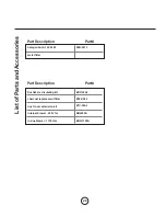
Page 20: ...on Part halogen bulb 12V 20 W metal filter Part Description Part Ductless recirculating kit charcoal replacement filter duct cover extension kit internal blower 600 cfm in line blower 1100 cfm ZRC 00A...

Page 21: ...21 www zephyronline com...

Page 22: ...22...

Reviews: