Manual RHGSE Operation and Maintenance Manual ZOM-11000-2 v2 rev E
Zephyr International llc
Page 18 of 40 United States Patent # 7,429,031 B1
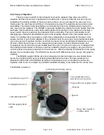
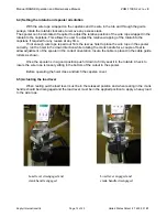
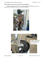
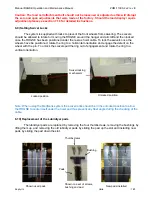
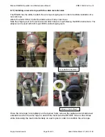
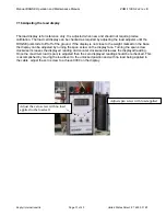
6.13) Using the Dryer
After extending the wire rope into the Rotatub, and filling the Rotatub with water, then applying
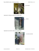
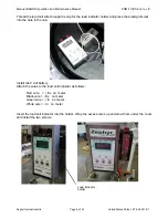
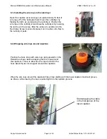
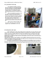
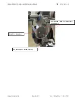
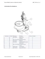
the load lever, and just prior to running the wire rope up into the helicopter hoist, attach an air line to
the airline connection located at the back of the Lubridryer. The air pressure required is 30 psi or 2 bar
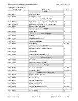
minimum. The air supply can be turned on or off via a ball valve. Replace the Lubridryer pads to clean
off any excess salt and turn on the valve attached to the back of the Lubridryer.
The compressed air will force the majority of the water off the cable prior to leaving the Lubridryer.
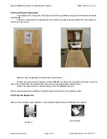
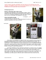
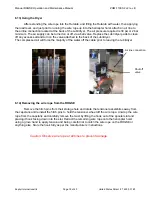
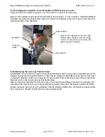
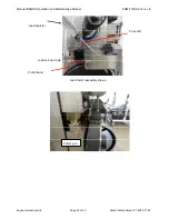
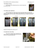
6.14) Removing the wire rope from the RHGSE
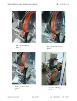
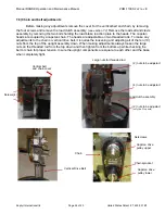
Remove the hitch pins from their storage hole and rotate the tensioner assemblies away from
the capstans and reinstall the hitch pins to hold the tensioner wheel off the wire rope. Unwrap the wire
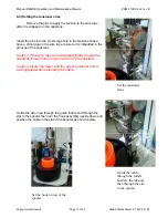
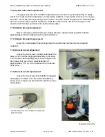
rope from the capstans and carefully remove the twist by lifting the hook out of the spooler slot and
placing it hook facing down into the slot. Retract the remaining wire rope onto the helicopter hoist
using a glove hand to apply tension and being careful not to catch the wire rope on the RHGSE or
anything else. Store the hook fully as per the manufacturers’ instructions.
Caution: Observe wire rope at all times to prevent damage.
Air line connection
Shut off
valve


