11
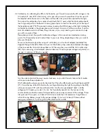
2. Headers: Your kit includes one 3-pin header. The process we use to solder these headers is to
hold it in place with one finger, apply some solder to the tip of your iron, and then quickly tack
in one lead on the bottom of the board (7). Make sure you don’t hold down the pin that you are
trying to tack down because the pin will heat up and it might burn you. Also make sure the
bottom of the header is flush with the top of the board as this is done. Once one lead is held in
place with the solder, we can put the circuit board in our clamp and solder the rest of the leads
(8). Then we always re-solder the tacked-in lead to ensure it is making a good connection.
Once the header is installed, place the jumper on the 2 pins labeled SPEAKER (9).
6
7
8
9
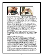
3. Power Light (LED): Place one of the green LEDs in the LED standoff (set the other LED aside for
later). Feed the LED leads in through the open end of the standoff, and thread the leads through
the two small holes in the other end. The green plastic body of the LED should be up against the
open end of the standoff.


