14
7. LDRs: As mentioned in the How It Works section, LDR stands for light dependent resistor and they
are used as the volume and pitch light sensors in the Noisette.
Your Noisette kit contains three LDRs. They have each been hand selected to have the correct
resistance range needed for their particular use in the Noisette. You will notice that one of these
LDRs has black dot on its backside. Set aside this LDR with the dot because it will be used for the
optocoupler, which we will assemble later. For now, we will be installing the two LDRs without
black dots.
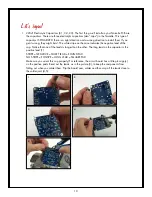
In this application, the body of each LDR is held 21mm above the circuit board, which allows it
to reside inside the LDR shield. We will use a piece of 21mm tall heat shrink tubing to space the
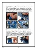
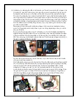
LDR the proper distance above the PCB. Cut two pieces of 2mm heat shrink, 21mm in length.
Basically, just cut the ~42mm long piece of heat shrink in two equal pieces (24). They don’t have
to be exact, they can be off by +/- 1mm.
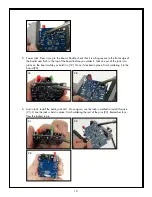
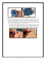
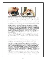
Place one piece of these pieces onto one leg of one of the LDRs (25). Install it in one of the LDR
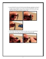
locations (26); please don’t shrink the heat shrink, it is only being used as a spacer. Make sure
the LDR is standing up straight, perpendicular to the surface of the circuit board. Also make sure
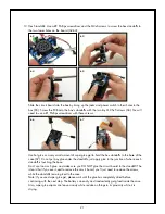
the body of the LDR is sitting on top of the heat shrink. It helps to hold the LDR in place as you
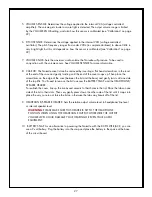
tack one leg down (27). Solder both LDRs in place and clip their leads (28,29).
24
25
26
27
28
29


