15
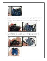
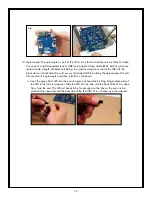
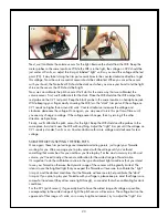
8. Trimmer Potentiometers: The Noisette contains four trimmer potentiometers (trim pots). VR1 – VR4
should fit into their locations with the adjustment screw located toward the right, as in the photo
(34).
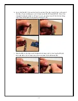
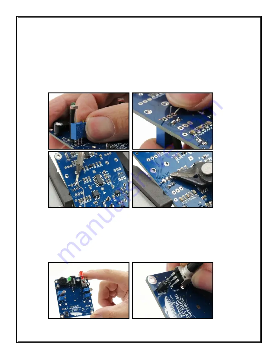
Use the tack-in method to solder these trim pots in. Hold the pot in place with one finger, apply
some solder to the tip of your iron, and then quickly tack in one lead on the bottom of the board
(31,32). Make sure the bottom of the trim pot is flush with the top of the board. Remember to
re-solder the tacked in lead to make sure it is making a good connection. Solder all four trim pots
to the board, then snip the leads (33).
30
31
32
33
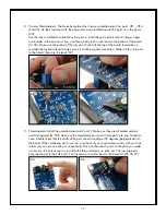
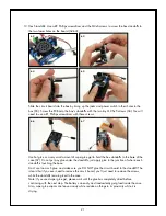
9. Potentiometers: Install the potentiometers (aka “pots”). Make sure they are all seated securely
and flush against the PCB; otherwise the completed board won’t fit properly into your Noisette’s
case. Double check that the shafts of the pots are all standing at 90 degrees (perpendicular) to
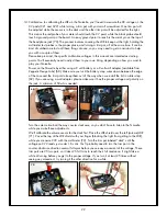
the board. When soldering do not use too much heat. If you cannot move quickly with your iron,
solder only one pin on each pot, sequentially. This will allow each pot to cool before you solder
its next pin. It is only necessary to solder the three small pins on each pot. The two large pins
help clip the pot to the PCB and it’s not necessary to solder them to the board (34,35,36,37).
34
35


