18
connected correctly then you should see a status bar indicating that the Quaverato is being
programmed.
5. If you got the message that the flash was a success (the status bar should reach 100%), then
unhook the ribbon cable from your Quaverato and continue with the next step. If you got any
other message then consult the Help file by pressing the “?” button. Review the troubleshooting
procedures.
PUTTING IT ALL TOGETHER
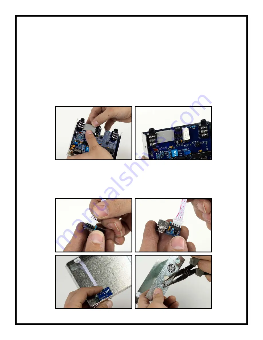
1. Apply the foam tape to the edge of the Quaverato’s circuit board as shown in the picture. Don’t
let it overhang the board (1,2).
1
2
2. Attach the 4-pin ribbon cable to the header on the MIDI board (3,4).
3. Attach the MIDI board to the chassis with the 1/8” jack nut (5,6). The board should be parallel
to the bottom of the chassis, with the solder side facing up. The ribbon cable should be laying
against the bottom of the chassis (5). Screw the nut onto the jack, but don’t over tighten it (6).
3
4
5
6
Summary of Contents for QUAVERATO MIDI MOD
Page 1: ...Assembly Instructions QUAVERATO MIDI MOD ...
Page 6: ...6 Figure 3 Component Values and Locations ...
Page 21: ......


