20
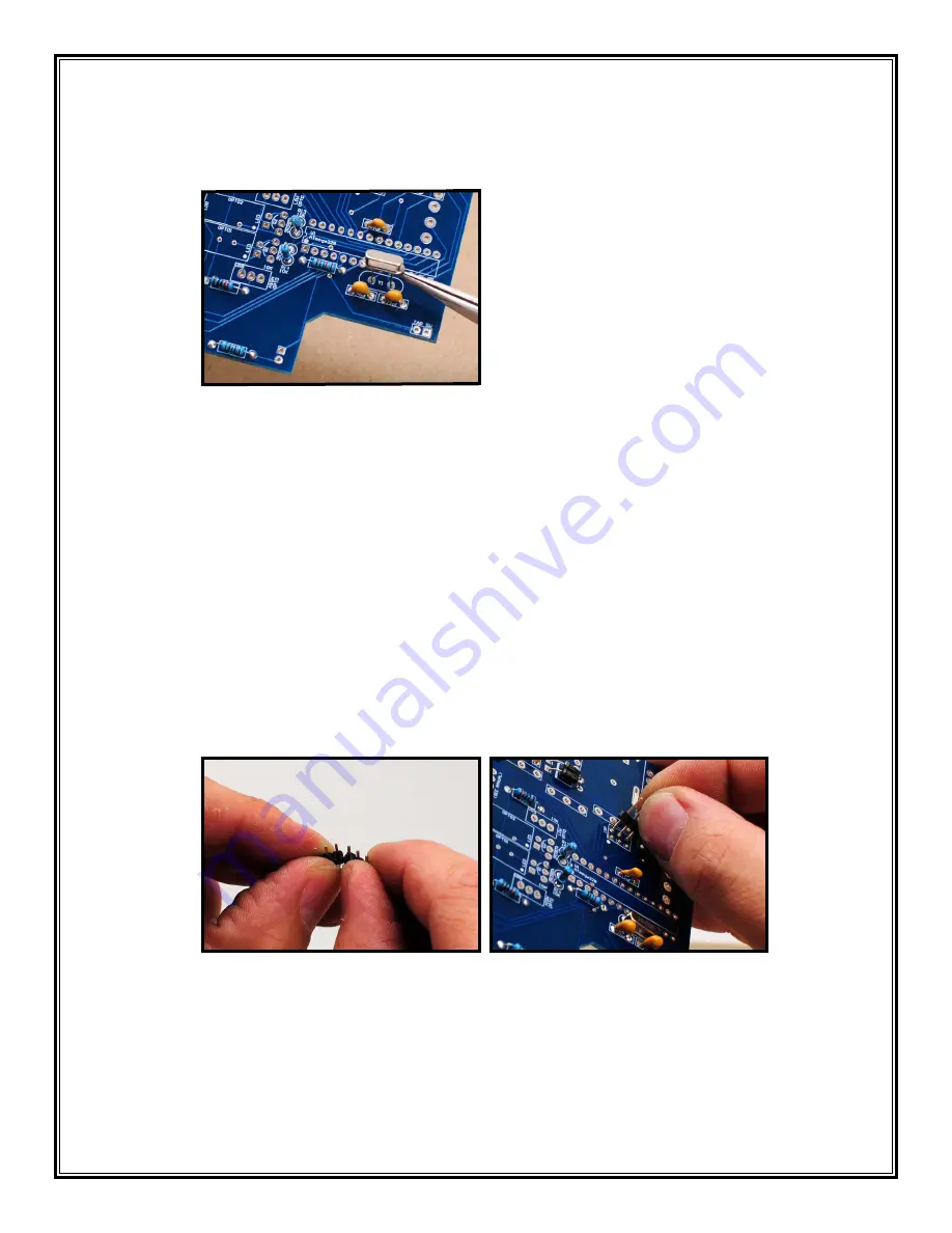
4. Crystal Oscillator (Y1): Place the crystal in the Y1 position on the PCB (the crystal is not
polarized) (39). Bend the leads out on the bottom; solder and clip the leads.
39
5. Headers (ISP and MIDI IN): We will now install the headers on the board to allow the Quaverato
to connect to other pieces of hardware.
a. By installing a 2x3 header array, you create an ISP (in-system programming) port. This is
a little socket that enables you to plug a cable into your pedal and upload (or “flash”) new
software onto the control chip (aka the microcontroller). The microcontroller in this kit comes
pre-programmed with the software needed to make your Quaverato work, but you can mod
or tweak the software and re-program the chip, if you are into that sort of thing. See the
Quaverato Owner’s Manual for more information about this. If you don’t ever plan on re-
programming your Quaverato then you can leave this header uninstalled.
Carefully break the header into three pieces: two pieces with three pins each, and one piece
with four pins. (Your kit may have been packaged with some pre-cut header pieces.) You can
use your fingers to do this (40). Insert the two 3-pin pieces in the pads markeed “ISP” (41).
The short pins go through the board; the long pins point up. Make sure the bottoms of the
headers are flat against the circuit board.
40
41


