22
6. Optocouplers: The optocoupler is the link between the digital (control) side of the circuit and
the analog signal path. There are two optocouplers: one that controls the low frequencies and
one that controls the high frequencies. Each optocoupler consists of a light dependent resistor
(LDR) and a light emitting diode (LED), both of which are sealed inside a length of of heat-shrink
tubing. The LDRs in this kit have been hand selected and matched to each other to within around
100 ohms at the same light intensity. This helps ensure that both signal paths are controlled
equally. We will first construct the optocouplers and then install them on the board.
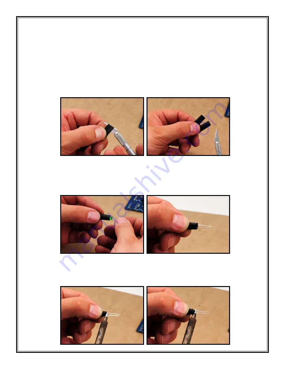
a. First cut the heat-shrink tubing into two equal lengths. (They both should be about 11/16”
[17-18mm] long.) (46,47)
46
47
b. Insert a green 5mm LED (don’t get them confused with the 3mm LEDs) into the end of a piece
of heat-shrink tubing (48). Proper placement of the LED in the tube is important. Slide the LED
into the tube until the back of the LED is about 5mm from the end. The LED just needs to be
far enough into the tube so the end can be pinched fully closed around the backside of the
LED (49). This will keep as much ambient light out of the tube as possible.
48
49
c. As you hold the LED in this position from the outside of the tube, carefully heat up the end
of the tube with your soldering iron until it closes around the LED leads (50,51). Once it has
stopped shrinking but while it is still very hot, use your pliers to pinch the shrunken tubing
closed around the leads to help seal the opening (52,53).
50
51


