10
will be installed on the “component side” of the board, which is the side that has the Zeppelin Design
Labs logo on it. The other side of the board is called the “solder side”, which, as the name implies, is
the side on which the legs of the components are soldered to the board. Proper technique for installing
and soldering components to a circuit board is demonstrated in our assembly reference video, but
there are several other great resources on YouTube under the search “soldering tutorial.” The general
procedure consists of the following:
1. Install the part on the “component side” of the board, by threading the wire leads through
the appropriate holes in the board. For your convenience, the board has silk screen outlines
indicating where the components should be placed, along with text indicating the part number
and often times the component value.
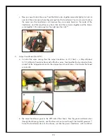
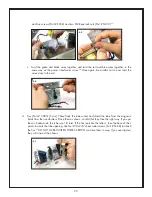
2. Hold the component in place with your finger and turn the board over.
3. Gently bend the leads out at about 45 degrees to keep the component from falling out of its
holes.
4. Install all of one type of component, bending each of the leads as they are installed.
5. Flip the board over solder-side-up, and solder all of the components in one pass.
6. Clip the leads off (with small diagonal cutters) right at the solder joint.
Let’s begin!
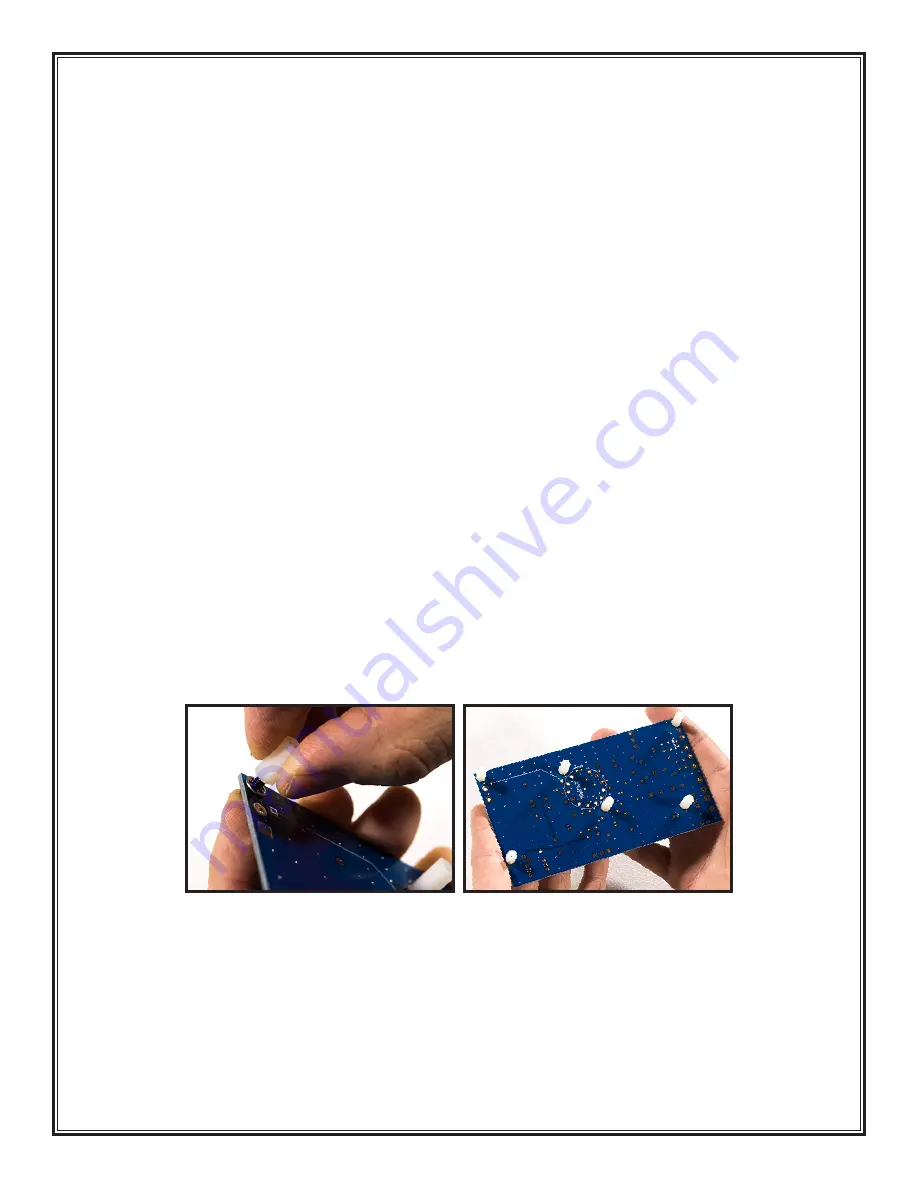
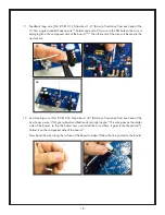
1. Standoffs (Part # SP11): Use 6 standoffs, 6 M3 screws (Part # SC38), and 6 lock washers (Part
# WA07). The plastic standoffs are installed on the solder side of the board, which means they
are screwed in from the component side. The lock washer goes between the PCB and the standoff
(not between the screw head and the PCB)
1
. Place the 6 standoffs in the locations indicated
below
2
.
2. Resistors: The value of resistors are given by a series of colored stripes on their body. There are
several tutorials on line describing how to decode these stripes, but we will identify each resistor
for you by simply naming the stripe colors, and giving you the value and the part number. Figure
2: Component Values and Locations on the next page is a handy reference. If you are color blind
or can’t see the stripes clearly, then you must use your digital multimeter to measure the resistance
of each resistor.
3. The hole spacing of most of the resistors on the circuit board allows the leads to be (gently) bent
1
2


