Z 2500-130/150
Installation
23
www.zepro.com
5.
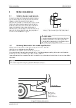
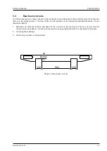
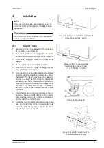
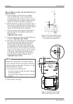
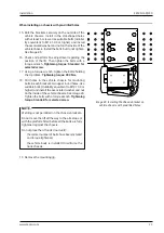
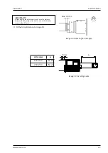
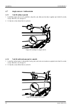
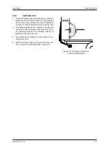
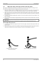
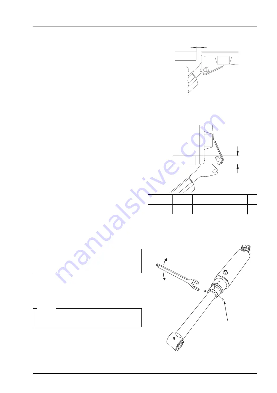
Test the lift by carefully raising it to the vehicle floor
level and tilting it to the vertical position. Check the
position in relation to the rear beam and side posts
of the vehicle. See illustration.
4.2.1
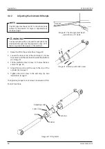
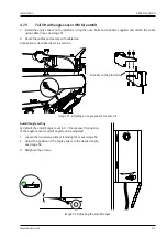
Adjusting the tilt angle
Do not adjust the cylinders before they are fitted
to the platform. The tilt cylinders are preset from
the factory.
NOTE.
1. Loosen the rubber bellows at the bottom where
they are secured with hose clips.
2. Tilt up and move both tilt cylinders all the way up.
Adjustment must always take place with full hy-
draulic pressure in the tilt cylinders.
NOTE.
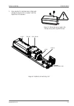
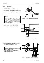
3.
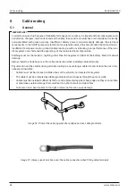
Loosen the three lock screws on the cylinder fitted
to the platform, see illustration.
Lock screws, 3 pcs.
Out
In
Image 32.
A
djusting the tilt angle
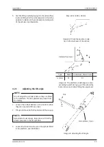
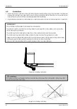
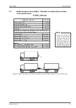
Image 33.
T
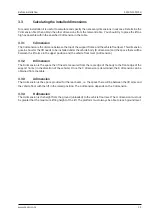
he platform underhang (A) varies
according to platform type, and this should be
taken into account when fitting the upper seal.
A (mm)
81
81
Type
Vehicle floor level
Steel
Aluminium, Plan 40 mm
A
Max. 40 mm, Min. 38 mm
Image 34.
C
heck the position in rela-
tion to the rear beam of the vehicle
Summary of Contents for Z 2500-130
Page 2: ......
Page 63: ...Z 2500 130 150 Specifications 63 www zepro com...

