Z 2500-130/150
24
Installation
www.zepro.com
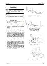
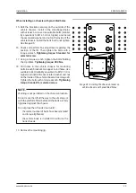
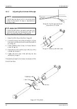
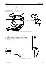
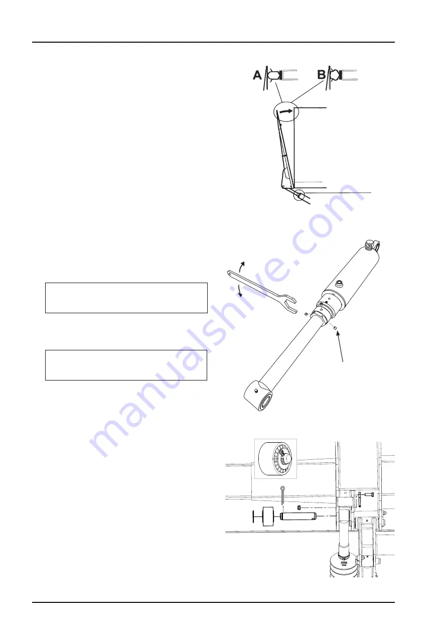
Locking screws, 3 pcs.
Out
In
Image 35.
A
djusting the fit to the vehicle body
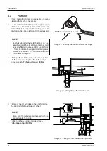
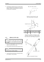
Image 36.
A
djusting the tilt angle
4.
Turn the adjuster sleeve until the platform fits
perfectly against the seal on the body.
Image 35
.
5. Undo the three locking screws on the other tilt
cylinder.
Image 36
.
6. Turn the adjuster sleeve until the tilt cylinder aligns
with the platform attachment point. See
Image 36
.
IMPORTANT
!
The max. length of both cylinders must be adjusted
equally to avoid unwanted bending forces.
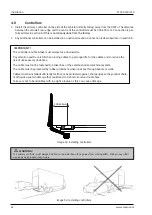
7. Install the other tilt cylinder on the platform attach-
ment point. Use the shaft and support wheel supplied.
IMPORTANT
!
Make sure the cylinder is installed with the grease
nipples facing up.
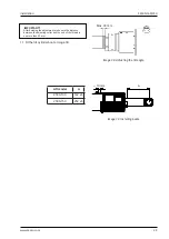
8. Tighten the bolts using a torque wrench.
Tightening torque: 80 Nm.
9. Adjust both cylinders alternately until the platform
touches the vehicle body; see
Image 35
(B).
10. Tighten the adjuster sleeve locking screws using
a torque wrench
Tightening torque: 3-5 Nm.
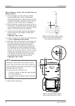
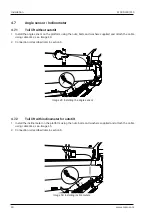
Image 37.
I
nstall the tilt cylinder on the platform
Summary of Contents for Z 2500-130
Page 2: ......
Page 63: ...Z 2500 130 150 Specifications 63 www zepro com...


