Z 2500-130/150
Connection
39
www.zepro.com
6
Connection
6.1
Cable grommet
6.1.1
Before connection
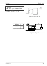
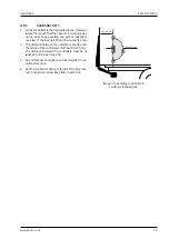
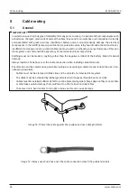
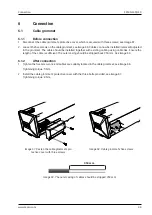
1. Disconnect the cable grommet’s protective cover, which is secured with three screws; see
Image 67.
2.
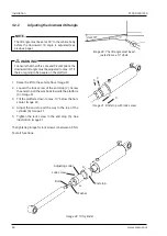
Loosen the five screws on the cable grommet, see
Image 68
. Cables can now be installed/removed/adjusted
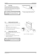
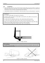
in the grommet. The cable should be installed together with existing cabling using cable ties. Ensure the
length of the cable is sufficient. The outer casing should be stripped back 350 mm. See
Image 69
.
6.1.2
After connection
1.
Tighten the five screws once all cables are suitably located in the cable grommet, see
Image 68
.
Tightening torque: 5 Nm.
2. Install the cable grommet’s protective cover with the three bolts provided, see
Image 67.
Tightening torque: 8 Nm.
Image 67.
F
asten the cable grommet’s pro-
tective cover with three screws
350 mm.
Image 68.
C
able grommet's five screws
Image 69.
T
he outer casing of cables should be stripped 350 mm.
Summary of Contents for Z 2500-130
Page 2: ......
Page 63: ...Z 2500 130 150 Specifications 63 www zepro com...

