background image

ZT MK2

Safety rules

11

www.zepro.com

3.2 

Calculating installation dimensions (standard lift)

For easier installation it is useful to calculate and specify the necessary dimensions in advance. Efforts 

should be made to install the lift as high as possible. (ZS)

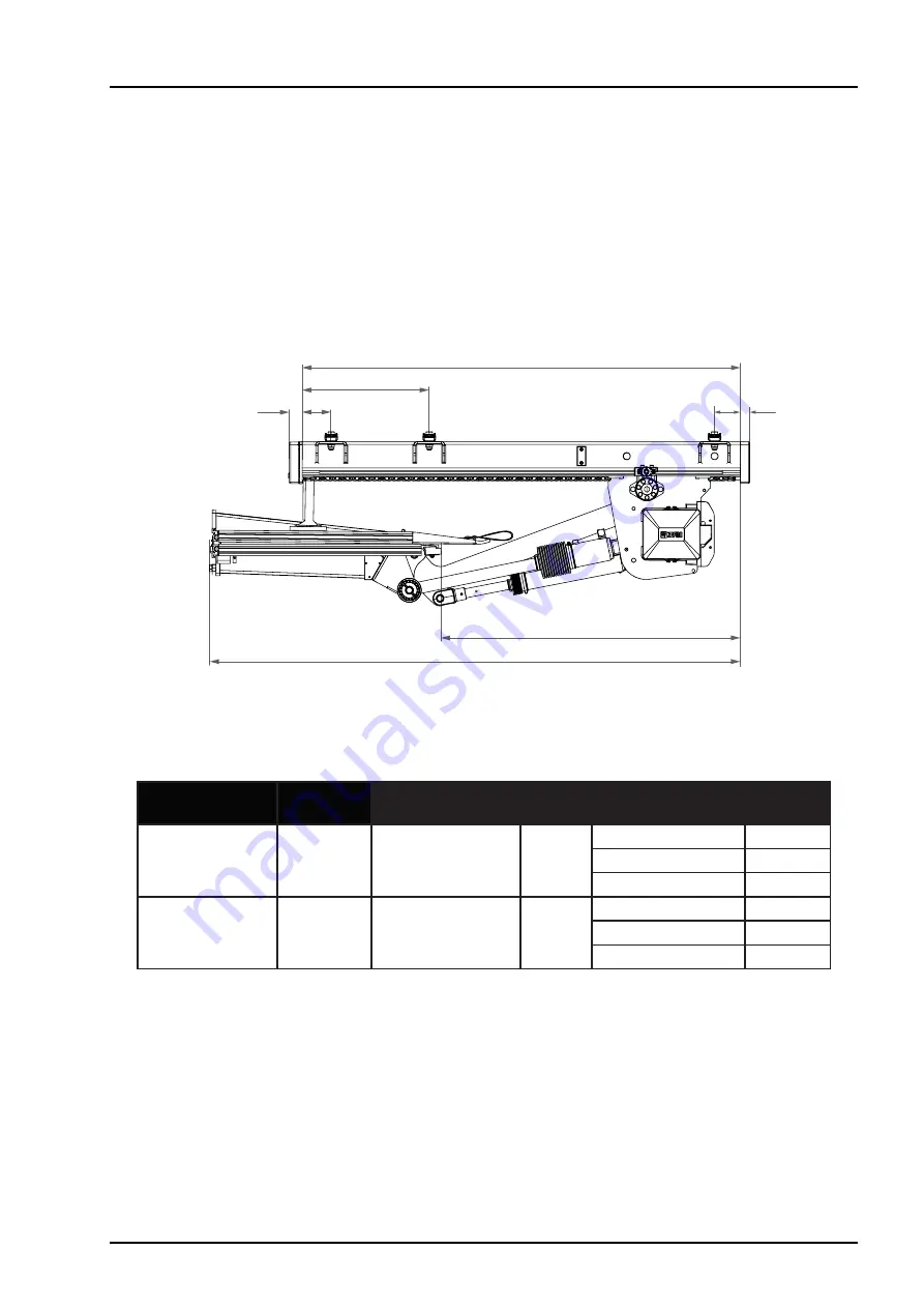
The platform and 1st boom combinations are optimized for minimum total length (O). Aim to install the slide 

profile in a position that allows the rear edge of the platform in the folded position to align with the rear edge 

of the vehicle body. In this way, it is guaranteed that the platform can be folded out.
The easiest way to calculated the installation dimensions is to use a CAD program. 2D drawings are available 

for downloading from www.c-office.com. For help with calculating installation dimensions, contact ZEPRO. 

Phone: +46 (0)10-459 05 04, Email: zeprotech@hiab.com.

Arm

Lifting 

height 

Slide profile 

(length)

B

Lift platform 

(length)

O

1565

1669

135

1356

1590

989*

1765 

1769

1965

1869

1565

1789

155

1542

1700

1109*

1765 

1889

1965

1989

* Applies to 50 mm bavetta. With a 70 mm bavetta, dimension (B) is reduced by 20 mm.

Length of slide profile

100

115

B

Total overhang (O)

495

Picture 9. Installation dimensions

46

36

All dimensions specified in millimetres

Summary of Contents for ZT 200 MK2

Page 1: ...ZEPRO Tel 46 0 10 459 05 00 E mail zeprotech hiab com zepro com 78617TL Installation instructions INFORMATION FOR SUPERSTRUCTURE BUILDERS AND INSTALLERS Tail lift ZT MK2 2021 06 29 ...

Page 2: ......

Page 3: ...lculating the installation dimensions Slimeline 13 3 4 Rear beam cut outs 15 3 5 Prepare the tail lift 16 3 6 Temporary connection of lift 18 3 7 Adjustment of slide profiles 19 4 Installation 20 4 1 Support frame 20 4 2 Setting the work position 21 4 3 Work position lock Option 22 4 4 Lift platform 23 4 7 Platform stop 25 4 6 Arm stops 25 4 5 Purging the cylinders 25 4 8 Transport stops 26 4 9 An...

Page 4: ... Autotilt 40 9 Lubrication and oil level check 41 9 1 Lubrication points 41 9 2 Oil level check 41 10 Marking 42 10 1 Max permissible load 43 10 2 Identification plate 44 10 3 Work area 44 10 4 Warning tape 44 10 5 Control device sticker 45 10 6 Danger area 47 10 7 Warning flags 47 11 Testing and verification 48 11 1 Static load test 48 11 2 Dynamic load test 49 11 3 Test of safety functions 49 12...

Page 5: ...rform a given operation 1 2 Configuration This tail lift is available in a many different configurations It is available in two versions Standard and Slimline Lift height lift capacity slider profile length and platform size may vary However the installation principles are the same whatever the configuration Standard or Slimline Lifting capacity 1500 2000 or 2500 Kg Max lift height 135 1356 mm 155...

Page 6: ...ct meets relevant requirements according to EN 1756 1 2001 A1 2008 1 6 Hydraulic oil If the hydraulic oil needs to be replenished only the oil recommended by ZEPRO is permitted to be used Hydraulic systems with hydraulic oil tanks without labelling are only permitted to be filled with highly refined mineral oil art no 21963 1 litre Hydraulic systems with hydraulic oil tanks marked with a specifica...

Page 7: ...in switch or by releasing the lift s main fuse in order to reduce the risk of the battery discharging The length of time the vehicle can be stored without the battery charge level becoming too low depends on the condition of the battery the charge level prior to storage and how much power other components in the vehicle take from the battery After a period of storage the battery must always be cha...

Page 8: ... closest part of the cylinder must be at least 40 mm Picture 6 The platform must not be tilted down by more than 10 from the horizontal 2 2 Connection of third party equipment is forbidden m WARNING Connecting third party equipment electric or hydraulic to Zepro tail lifts is forbidden Connecting third party equipment could interfere with the lift s system and its safety functions Risk of injury a...

Page 9: ...ons may be necessary Configurations highlighted in grey in the table below may mean that some modification is necessary for the tail lift underrun protection to meet statutory requirements If in doubt contact ZEPRO for support Model Arm Platform length Length of slide profiles 1590 1700 1850 Standard 135 1565 1765 OK 1965 OK OK 155 1565 OK 1765 OK OK 1965 OK OK OK Slimline 135 1565 OK 1765 OK OK 1...

Page 10: ...e beam all dimensions expressed in millimetres 3 1 2 Statutory dimensions Make sure the installation location allows the tail lift to meet the statutory dimensions for underrun protec tion when in transport mode Distance between the platform and the ground when the vehicle is unladen Max 450 mm for vehicles with air suspension Max 500 mm for vehicles with conventional suspension If the departure a...

Page 11: ...n this way it is guaranteed that the platform can be folded out The easiest way to calculated the installation dimensions is to use a CAD program 2D drawings are available for downloading from www c office com For help with calculating installation dimensions contact ZEPRO Phone 46 0 10 459 05 04 Email zeprotech hiab com Arm Lifting height Slide profile length B Lift platform length O 1565 1669 13...

Page 12: ... Lifting height H Cmax M N 135 1356 429 Max 389 Max 927 155 1542 518 Max 486 Max 1024 Picture 10 Installation dimensions P2 P1 H C Max N 538 M Picture 11 Installation dimensions 1905 810 1272 1200 1300 All dimensions specified in millimetres ...

Page 13: ...ows the rear edge of the platform in the folded position to align with the rear edge of the vehicle body This makes sure the platform can be folded out Arm Lifting height Slide profile length B Lift platform length O 1565 1734 135 1356 1590 1054 1765 1834 1965 1934 1565 1856 155 1542 1700 1176 1765 1956 1965 2056 Applies to 50 mm bavetta With a 70 mm bavetta dimension B is reduced by 20 mm Length ...

Page 14: ...max M N 135 1356 515 Max 397 Max 841 155 1542 604 Max 494 Max 938 All dimensions specified in millimetres Picture 13 Installation dimensions Picture 14 Installation dimensions 1905 810 1272 1200 1300 P2 P1 H C Max N 444 M All dimensions specified in millimetres ...

Page 15: ...uts depends on the calculated installed dimen sion A see illustration below 1 Measure and mark the location and depth of the cut outs on the rear beam The two cut outs must be centred on the rear beam i e both cut outs must be an equal distance from the mid point of the beam 2 Cut along the markings 3 Grind away any burrs or sharp edges Picture 15 Rear beam cut outs 245 245 A max 650 All dimension...

Page 16: ...ng the wing nut and corresponding screw C and pull out the hy draulic unit until the tank cap is accessible seePicture 19 m CAUTION Ensure that no cables are trapped or in any other way damaged when the control card is folded out or removed Do not pull out the hydraulic unit more than necessary make sure it is not pulled completely out of the frame as this can entail a risk of injury and damage to...

Page 17: ...ransport plug with the standard tank cap Picture 21 Hydraulic unit and control card CONTROL CARD TANK CAP MOTOR OIL TANK SOLENOID VALVE HOUSING 5 Check whether the hydraulic tank is fitted with a transport plug seal If so replace it with the regu lar tank cap supplied ...

Page 18: ...onnectors on the main power cables of the lift 3 When operating connect a cable between an available power supply connection and CS on the relay card to simulate switch CS in the On position Remove the jumper immediately after completed operation m WARNING Take great care when running the lift functions and make sure nothing gets trapped risk of injury and material damage 3 6 1 Battery maintenance...

Page 19: ...th of the chassis and centre the frame so the distance from the brackets to the centre of the frame is equally long on both the left and right hand sides Measure the distance between the brackets and the 1st boom s attachment 3 Tighten the nuts alternately until the clamp bears fully on the frame 4 Tighten the nuts Tightening torque 260 Nm IMPORTANT The frame brackets must be mounted completely pa...

Page 20: ...the frame in position to attain the correct dimensions in the X axis If necessary the rearmost position of the frame can be adjusted forwards in the slide profile with the help of the integrated adjustment for working position see section 4 2 4 Fit the support frame to the trailer frame using the clamping brackets Tighten the screws 12x Tightening torque 180 Nm IMPORTANT Welding is not permitted o...

Page 21: ... adjusting the working position forwards is limited by the length of the platform Make sure the platform can be unfolded into the intended working position after installation 1 Unscrew the rear end caps on both slide profiles 2 Loosen the adjusting screws counter nuts 3 Adjust the lift to the correct working position using the adjusting screws IMPORTANT Make sure the adjustment is the same on the ...

Page 22: ...nt The space for adjusting the working position forwards is limited by the length of the platform Make sure the platform can be unfolded into the intended working position after installation 1 Unscrew the end caps from the slide profiles 2 Insert the T shaped stop pins into the grooves on the slide profiles 3 Hook the lower part of the lock into a position on the chain that provides the correct wo...

Page 23: ...ws Tighten the screws Tightening torque 80 Nm 4 Fit one of the tilting cylinders to the platform Use the enclosed shaft and screw Tighten the screw Tightening torque 80 Nm NOTE Make sure the cylinder is installed with the grease nip ple facing up 5 Fit the support wheel on the shaft Secure with associated split pin NOTE Lubricate the bushings before installation Picture 28 Take care to provide ini...

Page 24: ...ing with the lock screw A See Picture 32 Tightening torque 3 5 Nm 11 Loosen the lock screw A on the other tilt cylinder 12 Turn the adjusting collar so the tilt cylinder aligns with the attachment on the platform and then fix the setting with the lock screw A 13 Fit the other tilting cylinder to the platform s attachment Use the enclosed shaft and screw Tighten the screw Tightening torque 80 Nm NO...

Page 25: ... the lift arms and the vehi cle floor rear beam The left and right end stops must be reached at the same time as high as possible on the left arm IMPORTANT Welding on the lift arm is not permitted Installation must take place on the vehicle body Picture 34 Fit end stops between the lift arms and the rear beam of the vehicle floor 4 7 Platform stop The platform is fitted with two platform stops ins...

Page 26: ...ps must always be installed in pairs one on each slider profile 1 Run the lift to transport position 2 Choose an appropriate hole pattern for installing the transport stop 3 If necessary cut the bracket above the mounting A 4 Bolt the transport stops to the left and right slider profiles Tightening torque 70 75 Nm Picture 36 Installing transport stops A ...

Page 27: ...ansport position 2 Unscrew the end caps from the slide profiles 3 On each slide profile unscrew the nut that tensions the chain and the two nuts that hold the bracket 4 Swap position of the left and right hand brackets Screw each bracket into place with the two nuts Tightening torque 80 Nm 5 Screw and tighten the chain by tightening the nut Tightening torque 50 Nm Picture 37 Alternative transport ...

Page 28: ...when delivered 1 When installing the angle sensor on the platform use the rivets supplied 2 Secure the sensor cable with cable ties IMPORTANT Route the cable between the platform and the lift arm tube such that it is well protected when the plat form touches the ground Leave enough slack to the first cable tie to avoid the risk of damage to the cable during lift operation Picture 38 Installing the...

Page 29: ...g cables to get longer life for the cables and to reduce the risk of unnecessary downtime The cable must not be fastened to brake lines or the vehicle s normal electrical system The cable must be protected by rubber grommets when it passes through beams or walls Cables must be installed sufficiently far from or be protected against sharp edges so they cannot chafe or otherwise sustain damage that ...

Page 30: ... when installing controller CD 4 on the tail lift 1 Fit the enclosed bracket to the tail lift 2 Install the controller on the bracket 3 In some cases the connector cabling may already be connected at the factory If not connection takes place later in section 6 Picture 41 Installation with bracket on tail lift ...

Page 31: ...p Motor unit 245 A 145 A Minimum recommended conductor cross sectional area copper cables plus and minus cables Control power cable 1 5 mm2 1 5 mm2 Main power cable L 8m 35 mm2 35 mm2 Main power cable L 8 15m 50 mm2 35 mm2 Main power cable L 15m 50 mm2 Battery Min capacity Imin available for lift 180 Ah 170 Ah Min voltage during operation Umin at lift 9 Volt 18 Volt Ensure that the lift has access...

Page 32: ...ommended that the CD 4 controller with main power switch be used The main power cable has to be run through a plastic collar and must not be fastened to the brake line or the vehicle s existing electrical system The main fuse has to be fitted close to the battery 1 Screw the fuse box in a suitable well protected place as close to the battery as possible 2 Run the main power cable from the battery ...

Page 33: ...amage WL1 U7 U6 U5 U5 U4 U4 U3 U2 U1 U0 U1 U2 U3 WL2 PA S5 S4 S3 S2 S1 S1 S5 S4 S3 S2 PA CS CS Down 2H Out Down Down C1 C1 Up Tilt In C2 Up Tilt C3 Up U0 Picture 44 Connecting control current on tail lift installed on trailer with main power switch 5 5 Open platform alarm When installing tail lifts on trailers it is recommended that alarms be installed for open platform This may be in the form of ...

Page 34: ... it should be done together with existing cabling using cable ties Ensure the length of the cable is sufficient for moving the control card The outer sheathing on cables that connect to the control card must be stripped 350 mm see Picture 47 6 1 2 After installing cabling 1 When all cables are suitably located in the cable grommet tighten the five screws see Picture 48 Tightening torque 5 Nm 2 Ins...

Page 35: ...cable 2 Run the cable and install with cable ties according to Picture 50 3 Connect the control device cables to ctrl 3 on the control card See section 6 3 4 Connect the warning light cable to WL1 on the relay card See section 6 3 Route the cable between the platform and the 1st boom s pipe so it is well protected when the platform hits the ground Leave enough slack to the first cable tie so the c...

Page 36: ... of physical damage Picture 51 Connection of controller and warning lights WL1 U7 U6 U5 U5 U4 U4 U3 U2 U1 U0 WL2 PA S5 S1 S4 S3 S2 S1 S5 S4 S3 S2 PA CS CS Down 2H Out Down Down C1 C1 Up Tilt In C2 Up Tilt C3 Up Ctrl 3 Ctrl 2 Ctrl 1 CD3 CD10 CD14 U1 U2 U3 U0 CD11 CD18 CD9 CD19 Black C1 White if available Brown Up Yellow Down Blue Tilt Green In Grey Out Black C3 White if available Brown Up Yellow Do...

Page 37: ...Connect the appropriate controllers and where applicable the warning lights 4 Run the cabling on the reverse of the control card and secure with cable ties 5 Fold in and secure the control card Ensure that no cables are trapped or in any other way damaged when the control card is folded out in IMPORTANT Picture 52 Installing cabling with cable ties ...

Page 38: ...ce the fuse 2 above see Picture 53 3 Connect the main power cable 3 to the connection point see Picture 53 4 Screw the cable connections and fuse into place using the knob 4 Install the cables at 90 or 180 from each other Install the fuse at right angles to the cables see Picture 53 The knob must lie against and centre the cable clip so that it does not come into contact with the bolt Incorrect in...

Page 39: ...ed by Approved by Stock nr Drawing nr Sheet Size Revision IS0 tolerances and drawing rules Tolerance Surface finish Welding 1 1 Drawn A CARGOTEC BRAND Used on ZEPRO El hydraulschema E H Schematic ZT Mk2 c010 ZT Mk2 c010 Z55515 78773TL 2021 03 04 MB ME MJ MK A A1 1 1 Z Lyften Produktion AB t GND 11 8 2 GND Indikerar jordanslutningar koppla dessa till någon av styrkortets jordpunkter Indicates groun...

Page 40: ...Revision IS0 tolerances and drawing rules Tolerance Surface finish Welding 1 1 Drawn A CARGOTEC BRAND Used on ZEPRO El hydraulschema E H Schematic ZT Mk2 c010 E AT ZT Mk2 c010 E AT Z55508 78757TL 2021 03 04 MB ME MJ MK A A1 1 1 Z Lyften Produktion AB t GND 11 8 2 GND Indikerar jordanslutningar koppla dessa till någon av styrkortets jordpunkter Indicates ground connection connect these to ground co...

Page 41: ...and left side 2 Lift arm lift cylinder and tilt cylinder frame bearings right and left side 3 Slider wheels right and left side 9 2 Oil level check Check the oil level in the tank top up if necessary If the hydraulic oil needs to be replenished only the oil recommended by ZEPRO is permitted to be used Hydraulic systems with hydraulic oil tanks without labelling are only permitted to be filled with...

Page 42: ...0 03 04 Picture 58 Overview of labelling 10 Marking Below an overview of the location of the different markings is shown Image of marking and further informa tion can be found under the each subchapter for subsequent pages 10 1 10 5 10 3 10 4 10 5 10 6 10 7 ...

Page 43: ...r the model concerned next to all control device stickers Picture 59 Max permissible load for load capacity 1500 kg load centre distance 750 mm Picture 60 Load diagram for load capacity 2500 kg load centre distance 750 mm Picture 61 Load diagram for load capacity 2000 kg load centre distance 750 mm ...

Page 44: ...lowing infor mation Type of lift Max permitted load in kg Production number Year of manufacture Address and tel no of manufacturer Country of manufacture Type number for approved underrun protection RUPD Type number for electromagnetic compatibility EMC 10 3 Work area Affix the sticker clearly visible on the rear of the vehicle Picture 64 Warning tape 10 4 Warning tape Affixed along the platform e...

Page 45: ...020 03 04 10 5 Control device sticker Affix the controller sticker next to the relevant controller The stickers are available in standard versions and in reversed version Option for affixing on the opposite side of the vehicle Make sure the stickers are affixed so the image of the vehicle tail lift on the sticker is in the same direction as the vehicle on which it is affixed Picture 67 Standard mo...

Page 46: ... with the two middle symbols for the tilt down and tilt up functions Additional autotilt sticker for CD 19 2021 06 01 78877TL www hiab com Additional autotilt sticker for CD 9 www hiab com 77663TL 2020 02 10 A A www hiab com 55053TL 2020 03 04 www hiab com 78888TL 2021 06 11 A A www hiab com 55057TL 2020 03 04 A A Additional autotilt sticker for CD 3 Affix the additional CD19 autotilt sticker on c...

Page 47: ...er area If one is fitted affix the sticker on the inside of the vehicle body next to the hand control unit 10 7 Warning flags Attach warning flags as close as possible to the top and edge of the platform where there is no risk of them coming loose when the platform is lowered to the ground Swage the tracks together to secure the warning flags ...

Page 48: ...atform according to the table for the respective tail lift model lifting capacity Remove the test load from the platform Repeat the measurement of A B C D and verify that there has been no deformation of the lift or its fixing 11 1 2 Drift Place a test load on the platform according to the table The tail lift must be at the same level and angle as the vehicle floor Leave the test load for 15 minut...

Page 49: ...functions must be tested Check That the red light in the driver s cab turns off when the platform is in transport position and that it turns on when the platform is run out That the tail lift cannot be activated if the cabin switch is in the off position That the tail lift cannot be activated when the main switch fuse is removed That the overflow valve is activated when the lift is operated up to ...

Page 50: ...y of the lift s parts are heavy requiring the use of lifting equipment to get them in place Make sure the weight of the parts does not exceed the maximum permitted load of the lifting equipment Complete lift chassis ZS S MK2 without platform slider profile 1850 mm Lifting capacity Arm Weight 1500 135 369 Kg 1500 155 379 Kg 2000 135 373 Kg 2000 155 383 Kg 2500 135 378 Kg 2500 155 389 Kg Shorter sli...

Page 51: ......

Page 52: ...s Hiab is a world leading supplier of equip ment intelligent services and digital solutions for on road load handling As an industry pioneer our company commitment is to increase the efficiency of our customers operations and to shape the future of intelligent load handling ...

Reviews: