Doc Number 801-00015, Version 1.1, Copyright © 2010 Zep Solar, Inc.
PAGE:
4 of 28
ZEP SYSTEM II INSTALLATION MANUAL
2.2 > Installation Safety
1. Check applicable building codes or refer to a structural engineer to ensure that the structure upon
which the Zep System is being installed can properly support the array under live load conditions.
2. Ensure that all lag screws or alternative methods of attachment have adequate pullout strength
and shear capacity for the application.
3. The Zep System must be installed over a fire resistant roof covering rated for its application.
4. The Interlock, Leveling Foot, and Ground Zep should be installed only with the use of the Zep
Tool or Flat Tool provided by Zep Solar.
5. During the installation, wear suitable protection such as non-slip construction gloves to protect
your hands from injury from sharp edges.
6. Do not expose the Modules to excessive loads or deformation such as twisting or bending.
3.0 > Zep System II Overview
Zep System II offers an ultra rapid method for installing and electrically grounding solar arrays. In
addition to the application-specific attachment hardware, an entire array can be installed with only
three parts — the Interlock, the Leveling Foot, and the Ground Zep. Zep Solar also offers accessory
items such as the Zep Comp Mount and Zep Wire Clip.
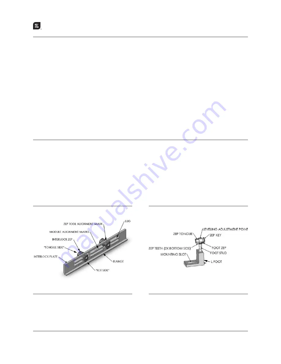
Figure 3.0A
— Interlock
The Interlock installs in the nominal east-west dimension and
provides both structural and ground bond connections in both
east-west and north-south dimensions.
Figure 3.0B
— Leveling Foot
The Leveling Foot installs into the Zep Grooves and resides at
locations along the array’s horizontal seams.


