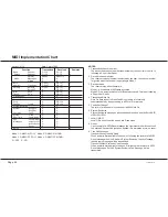
background image

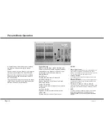
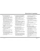
Setting Up the Desk for Programming
1 Set ALL faders at zero, set Grand Master to

full.

2 Turn the Mode switch to Program. Program

light will come on.

3 Push the Master A fader to full.

4 Check memory Page is showing ‘1’.

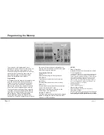
Programming a Memory
1 Select the memory Page required using the

Page ‘+’ and ‘-’ controls.

2 Press the Flash/Preview button to select the

memory (1-12) that you wish to program. The
Preview lights will show any previously
programmed scene; the Preview light of the
memory selected will flash slowly and the
Page display will change from 1 (for example)
to P1, a reminder that the page selected is
being previewed.

3 Set up a scene on Preset A.

4 Briefly press the Program  button to transfer

the Preset A levels to memory. The new
memory is immediately displayed on the
yellow Preview leds to verify that this
information has been recorded.

5 Repeat steps 1 to 4 to program additional

memories.

Clearing a Memory
1 Select a memory to be programmed or

program a new memory as described above.

2 Set Master A down to zero.

3 Briefly press Program  to clear the memory by

storing a scene with all levels at 0. Any
preview lights that were on go off.

Blind Programming
This is possible using the Level Match feature
described on Page 11.

/p9/3

HINTS

*

Programming Appears Not To Work

Check that the Grand Master and Master A are up to full,
since with Master A at zero, a blank memory will be
programmed. Simply fade up the Grand Master or Master A
and reprogram the memory.

*

The scene recorded is not the scene that was
wanted.

Check that none of the Memory Masters or the Effects Master
were up whilst you were programming. If any of these masters
were on, this will be shown on the Output Lights and the
memory that will be recorded will be the mixture of levels
set by Preset A and levels set by the Memory Masters 
that
were up. This is an essential feature of the desk.

*

Reprogramming a Memory

If the memory chosen is not empty (shown by the preview
lights coming on), pressing the Program button will overwrite
any previous information with the current settings of Preset A;
the old memory will be lost.

*

Changing the Memory Selected

To change the memory that you have selected within a Page,
simply press another memory Flash/Preview button. To
remove the memory preview information from the Preview
lights in Run, press the Flash/Preview button of the memory
once again.

*

‘PC’ in the Page Display

When ‘PC’ is shown (Preview Ch), this means that ‘Ch’ was
showing in the Page display when the memory was selected.
Pressing the Flash button again will return the display to ‘1’ or
using the Page +/- buttons will move to the correct Page
required.

Programming the Memory

7359500/p9/3

Page 9

Summary of Contents for Lightmaster XL

Page 1: ...Lightmaster XL Manual...

Page 2: ...n only E OE Zero 88 Lighting Ltd 1995 Stock No 73 595 00 Software version 6116 Zero 88 Lighting Ltd Usk House Llantarnam Park Cwmbran Gwent NP44 3HD U K Tel 44 0 1633 838088 Fax 44 0 1633 867880 e mai...

Page 3: ...12 Programming controls 12 Programming a Sequential Effect 13 Editing a Step in a Sequential Effect 13 Previewing and Running Sequential Effects 13 Programming the Audio Effect 13 Previewing and Outpu...

Page 4: ...esk Memory Organisation 22 Advanced MIDI Programming 22 Set up the desk to respond to the Octave starting with Middle C Note Value 60 22 Set up the desk to respond to external Program Change commands...

Page 5: ...allows storage and retrieval of lighting scenes using the B preset as memory masters The Effects section allows storage and retrieval of chase and audio effects The MIDI function allows the desk to o...

Page 6: ...odes of operation GRAND MASTER Sets maximum level for all outputs FLASH FUNCTION Determines the function of flash buttons see notes NOTES Flash Functions Off Flash Buttons do not function Flash Pressi...

Page 7: ...l channels or memories are flashed OUTPUT LIGHTS Brightness indicates current channel output FADE TIME Sets the time for a scene to fade in or out NOTES Master Fader Levels For each channel the level...

Page 8: ...Function to select Flash 2 Press one or more individual channel Flash buttons The channels selected have been added into the scene at the level set by the Grand Master Soloing to a Channel 1 Change th...

Page 9: ...d PROGRAM Transfers levels currently output to memory MASTER A Sets maximum channel level within memory PRESET A Sets individual channel levels for programming FLASH PREVIEW BUTTONS Selects one of the...

Page 10: ...1 p9 3 HINTS Programming Appears Not To Work Check that the Grand Master and Master A are up to full since with Master A at zero a blank memory will be programmed Simply fade up the Grand Master or Ma...

Page 11: ...ge or Sequence will only change when the fader reaches 0 or the Flash button released This feature is called Page Overlay The operation of this feature is shown by the slow flashing of the appropriate...

Page 12: ...annel faders in turn until the associated channel Preview light is on continuously Be careful When the Preset A fader level is at the recorded level the fader catches the level and then has LIVE contr...

Page 13: ...d level in four harmonic bands Bass Low Mid High Mid Treble For Ripplesound as the sound level increases the level of audio memory A1 is increased to 100 first followed by A2 being increased to 100 un...

Page 14: ...olo the sequence using the Effects Flash Preview button Turn the Speed knob to Manual then press Go to step through the sequence manually Programming the Audio Effect 1 Set the Mode switch to Program...

Page 15: ...puts next step of stopped chase sequence FLASH Flashes Solos the effect NOTES Auto Varispeed Bass Chase Auto Chase requires no sound input with Chase Speed determined directly by the speed control Var...

Page 16: ...p Number using the Go button 4 Press Program once to program zero levels into the audio memory selected 5 Repeat steps 3 and 4 for any other audio memories that need clearing NOTES The letters ER or N...

Page 17: ...e Step No display flashes IC Insert Card until a card is inserted or the Go button is pressed again Using Compare CP If the Card contents are not the same as the desk contents NO with two flashing dot...

Page 18: ...If there is no desk channel driving the DMX channel the display has a in it 3 Press the Memory Page buttons to examine the channels patched to the other DMX outputs To re patch the DMX channels 1 Set...

Page 19: ...nd that is played When a voice is changed a signal called a Program Change is sent on the Transmit channel assigned to the instrument Any device which has been set up to receive data on this channel w...

Page 20: ...set to the first note of the first octave drives desk channel 1 the first note of the second octave drives channel 1 also and so on See paragraph section on Note Numbers opposite The default is Sets...

Page 21: ...ry Page display shows Ch 2 Connect a MIDI cable from main desk MIDI OUT connector to the secondary desk MIDI IN connector 3 Press Memory button on the main desk to select du 4 Press the Go button on t...

Page 22: ...the Slave s as required Sequences These are driven from the Master effects section For sequences to work properly they must be programmed very carefully For example Setting up a 24 channel chase on t...

Page 23: ...is is how they will be used For this example program scenes to fill all the memories in Pages 3 6 and 8 Connect a MIDI cable from the keyboard MIDI OUT port to the desk MIDI IN port Check the keyboard...

Page 24: ...36 3 37 38 39 40 41 42 43 44 45 46 47 48 4 49 50 51 52 53 54 55 56 57 58 59 60 5 61 62 63 64 65 66 67 68 69 70 71 72 6 73 74 75 76 77 78 79 80 81 82 83 84 7 85 86 87 88 89 90 91 92 93 94 95 96 8 97 98...

Page 25: ...operating in Mode 1 3 Receiver mode The receiver may either operate in Mode 1 All channels of MIDI data accepted Mode 3 Only a single channel of MIDI data accepted This is set following a Super User R...

Page 26: ...that will allow some desk operations to proceed despite the fault and those that prevent the desk working completely Faults that allow desk operations to continue Display Page Step No Chaser frame mem...

Page 27: ...operation the fuse must be 100mA AntiSurge T For 100 130 V ac operation the fuse must be 250mA AntiSurge T DO NOT USE THE WRONG VALUE OR TYPE WARNING Mains Supplies If the Lightmaster XL s memory is f...

Page 28: ...Zero 88 Lighting Ltd Usk House Llantarnam Park Cwmbran Tel 44 0 1633 838088 Gwent Fax 44 0 1633 867880 NP44 3HD Web www zero88 com U K E mail sales zero88 com 24Hr Answer Phone...

Page 29: ......
Page 30: ...Gradav Hire Sales Ltd The Power House Elstree Film Studios Shenley Road Borehamwood Herts WD6 1JG Phone 020 8324 2100 FAX 020 8324 2933 Email office gradav co uk Web www gradav co uk...

Reviews: