background image

Installation & Operation  •  7

INSTALLATION & OpERATION































































































































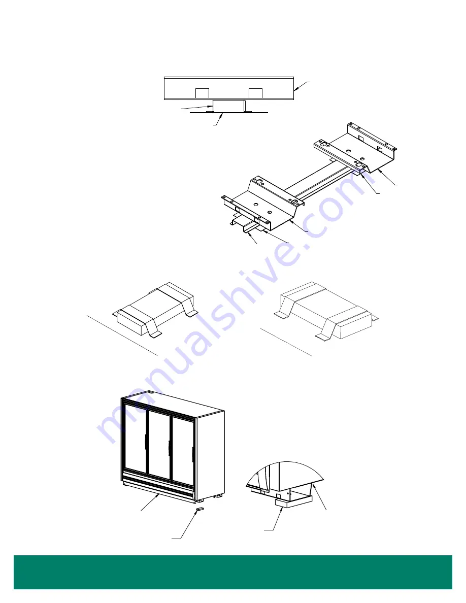
Hat Channel Rail

Hat Channel Rail

Shim

Shim

Shim

Base

Base

Base

 Position hat channel rails with tape up. Place shims 

perpendicularly under the hat channel rails.


ƒ

2-door cases get 2 hat channel rails.


ƒ

3 and 4-door cases get 3 hat channel rails.  

Do not position under the drain hub.


ƒ

5-door cases get 4 hat channel rails.

 FIGURE 7: Hat Channel Rail Orientation

 FIGURE 8: Tape Shims on the Floor Under Each Base or Hat Channel Rail

Cas

e F

ron

t

Case

 Fr

ont

Placement 

under Bases

Case Front

Case Front

Placement under 

Hat Channel Rails

 FIGURE 9: Shims Under Bases (Without Hat Channel Rails)

Shims must be placed under the front 

and rear bends of each base to prevent 

the base from warping/buckling.

Case

Shims

Case

Shims

Both corners of the base 

must be supported by shims 

to prevent base buckling

DWG. NO. SP-6006-1  REV.  A

Display Case

Shims

Shims

Display Case

Summary of Contents for CRYSTAL MERCHANDISER RVMC24

Page 1: ...COMPLIANT 66 0014 REV G Jul 2022 ZERO ZONE CRYSTAL MERCHANDISER COOLERS RVMC With CoolView Doors and ChillBrite LED Lighting INSTALLATION OPERATION MANUAL ...

Page 2: ... Bumper 19 Top Trim 19 CoolView Doors 19 CoolArc Door Handles 19 Hold Open Bracket 19 Door Gasket 20 Door Closer Adjusting Door Tension 20 Removing a Door 20 Installing a Door 20 Rear Load Cases 21 Shelves Stocking Product 21 REFRIGERATION 22 Mechanical Components 22 Evaporator Fans 22 Expansion Valve 22 Additional Valves 22 Refrigerant Piping 22 Leak Check Evacuation Charging 22 Operation Set Poi...

Page 3: ...hall not be covered by this warranty Extended Warranties In addition to the standard limited warranty for further consideration the Seller will extend to the original purchaser prior to shipment a limited extended warranty on the compressor only following expiration of the standard warranty The Seller agrees to repair or exchange at its option or provide reimbursement for such exchange as directed...

Page 4: ...ems arise call Zero Zone at 800 247 4496 Any change to a Zero Zone product made during the installation start up or at any other time must be submitted in writing to Zero Zone for approval and be approved by Zero Zone in writing prior to commission The product warranty is voided when any unapproved change is made to a Zero Zone product Manufacturer Zero Zone Inc 110 N Oakridge Dr North Prairie WI ...

Page 5: ...L 471 Commercial Refrigerators and Freezers ANSI Approved equipment certified by ETL ASHRAE Standard 72 Method of Testing Commercial Refrigerators and Freezers ANSI Approved AHRI 1200 Performance Rating of Commercial Refrigerated Display Merchandisers and Storage Cabinets ANSI Approved DOE Compliant All U S Sales and U S Territories ASHRAE Standard 72 specifies the test conditions for the equipmen...

Page 6: ...labeled x 1 has a packet attached to the shelving that contains touch up paint Every case in a lineup has a packet attached to the shelving that contains important information about the case and or lineup and if applicable special instructions for installing ordered options Bumpers and kickplates are shipped on top of the case Shelves for the case are tie wrapped and blocked into the individual ca...

Page 7: ...ct them from Johnson bar damage Make sure that a forklift with the proper fork dimensions is available Forks must be 48 long 1 1 2 to 1 3 4 thick and no more than 4 wide to fit the bases Refer to the table below for instructions CASE MODELS INSTRUCTIONS 2RVMC24 Forks must extend 20 to 24 under the case from either end 3RVMC24 Forks must extend 26 to 30 under the case from either end 4RVMC24 Forks ...

Page 8: ...e 5 Refer to the fixture plan or floor plan 2 Snap a chalk line at the locations for the front and back positions of the bases 3 Mark locations of all joints both front and back 4 Using a laser level or transit find the highest point along both base position lines Using the high point as a reference mark the difference directly on the floor to each base both front and back See Figure 6 5 If your c...

Page 9: ...hat channel rails Figure 7 Hat Channel Rail Orientation Figure 8 Tape Shims on the Floor Under Each Base or Hat Channel Rail Case Front Case Front Placement Under Bases Case Front Case Front Placement Under Hat Channel Rails Figure 9 Shims Under Bases Without Hat Channel Rails Shims must be placed under the front and rear bends of each base to prevent the base from warping buckling Case Shims Case...

Page 10: ...Operation Figure 10 RVMC30 Base Locations 2RVMC30 3RVMC30 4RVMC30 5RVMC30 Drawings are top views with bases shown under the case The front of the case is toward the bottom of the page Case length does not include end panels 2 1 2 wide each ...

Page 11: ...Operation Figure 11 RVMC24 Base Locations 2RVMC24 3RVMC24 4RVMC24 6RVMC24 Drawings are top views with bases shown under the case The front of the case is toward the bottom of the page Case length does not include end panels 1 1 2 wide each ...

Page 12: ...ion Figure 12 RVMC30D DeepCase BaseLocations 2RVMC30D 3RVMC30D 4RVMC30D 5RVMC30D Drawings are top views with bases shown under the case The front of the case is toward the bottom of the page Case length does not include end panels 2 1 2 wide each ...

Page 13: ...on Figure 13 RVMC24D Deep Case Base Locations 2RVMC24D 3RVMC24D 4RVMC24D 6RVMC24D Drawings are top views with bases shown under the case The front of the case is toward the bottom of the page Case length does not include end panels 1 1 2 wide each ...

Page 14: ...depth and Deep cases should be set with a slight backward tilt to offset the forward lean of a fully loaded case We recommend an additional 3 8 of shims be installed under the front bases after the case is leveled See Figure 14 Note Do not add extra shims under Ultra Narrow cases Figure 14 Tilt Back Add 3 8 of shims under front bases for proper tilt back Approximate tilt back of empty case 1 on st...

Page 15: ...nder any bases or hat channel rails with gaps taller than one shim Do not place shims between bases and hat channel rails Total height of shims should be less than 3 4 Lineup Assembly Zero Zone display cases have been designed for continuous display so that multiple cases may be joined together to create a lineup of any desired length The lineup will be ready for assembly after removing the packag...

Page 16: ... There are 2 types of insulated dividers 1 Between a Crystal cooler and a different case The insulated divider has a panel on each side with nut inserts in the panels each side is bolted to the respective end frames Do not pull cases together using joining bolts 2 Between 2 Crystal coolers The insulated divider uses a thru bolt design The divider is attached to one of the cases using short bolts f...

Page 17: ... when the cases are pushed together and excessive caulk may squeeze out of the joint Wipe away any caulk that squeezes out Butyl caulk will not mix with silicone sealant used for NSF sealing which will affect adhesion of both 1 Apply 3 8 thick beads of Butyl caulk along the ceiling rear wall and bottom of the case where indicated by the dashed lines in the drawing Caulk must be continuous with no ...

Page 18: ...aulked and joined before NSF sealing Wipe away any Butyl caulk that squeezes out of the case joint Butyl caulk and silicone sealant will not mix which affects the adhesion of both See Figure 18 on page 15 1 Apply silicone based sealant in small continuous beads where indicated by the dotted lines in the drawing Do not thin or feather as that will affect adhesion 2 Sealant must be added between cas...

Page 19: ...per gaps loosen the screws holding the top or bottom door mounting plates then shift the door Figure 20 Anchoring Ultra Narrow to Another Case 7 1 1 4 DETAIL A CASE TO CASE TRIM 37 0528 XP1 SCREW CASE TO CASE TRIM TO END TRIM ON VMC24BBUN DOUBLE STICK TAPE THE CASE TO CASE TRIM TO THE 2RVMC24UN END PANEL RELEASED 3 GAP BETWEEN CASES 1 0 7 9 1 0 4 7 9 1 1 2 A LEFT SWING DOORS RIGHT SWING DOORS FREN...

Page 20: ... There is no room in front of the base for the drain pipe because the kickplate installs directly to the front of the bases Install the tee to the outlet pipe and a drain trap to the tee Plug the open end of the tee using the clean out plug supplied with the drain trap kit The drain line must be pitched away from the case The tee drain trap and plug are supplied with the case The drain trap must b...

Page 21: ...ttaching the bumper See Door Leveling Door Sag Sawtooth on page 17 Top Trim Top trim is factory installed and it hides the door hardware located on the top exterior of the case Joint splices are shipped loose and must be field installed at the upper case joints CoolView Doors Door leveling must be completed before attaching the bumper and kickplate See Door Leveling Door Sag Sawtooth on page 17 CO...

Page 22: ... necessary to remove them REMOVING A DOOR 5 Remove the top case trim that covers the door hinges 6 Turn door tension screw clockwise until door does not close on its own This removes tension between the door and torque adjuster 7 Disconnect the hold open bracket from the bottom of the door See Figure 25 on page 19 8 Remove shoulder bolt and bushing on the top of the hinge side of the door See Figu...

Page 23: ...a 10 angle Optional shelf assemblies are available that may be tilted at 5 10 or 15 angle The case may be stocked with product after it has operated at least 24 hours with correct case temperature and proper control operation When stocking the shelves leave a gap between the product and the shelf above which allows an air curtain on top of the product Product should not extend beyond the front of ...

Page 24: ...t hand side of the coil for venting and draining the system An additional tap is provided on top of the case to allow for venting when the system is drained Refrigerant Piping Correct refrigeration line sizing and industry standard installation practices are essential for proper system operation Zero Zone offers many refrigerant choices We recommend using the Sporlan Virtual Engineer Toolbox to ca...

Page 25: ...ld installation instructions are packaged with the NSF thermometer SETTING COOLER Defrost Type Off Cycle Electric Frequency 3 Per Day 2 Per Day Duration 45 Minutes 30 Minutes Figure 34 Defrost Settings Figure 33 Case Temperature Internal Control Options SETTING COOLER Evaporator Temp 28 F Return Air Temperature Set Point 33 F Return Air Temperature Differential 4 F Discharge Air Temperature Set Po...

Page 26: ...circuit The electrical box is mounted on the exterior top right of the case The box includes the power connection and power supplies for the LED light sticks The light switch is located on the interior ceiling to the right of the coil cover See Figure 35 Black and white wires and wire nuts are supplied and the wire nut must be connected inside the electrical box A ground connection should also be ...

Page 27: ...false ceilings fans and fan plenums 6 If the case is equipped with a condensate pan and pump the drain should be blocked before washing coils Water can be removed with a shop vacuum 7 Coils may be cleaned with a garden hose or pails of water If the case is equipped with a condensate pan and pump cases should be cleaned with a minimal amount of water so the evaporator pump and drain pans do not get...

Page 28: ...M 2022 Zero Zone Inc All Rights Reserved Jul 2022 For other technical support please refer to the Technical Resources page at WWW ZERO ZONE COM or contact the Zero Zone Service Department at 800 247 4496 All specifications subject to change without notice ...

Reviews: