18 • Installation & Operation
INSTALLATION & OpERATION
BOTTOM MOUNTING PLATE
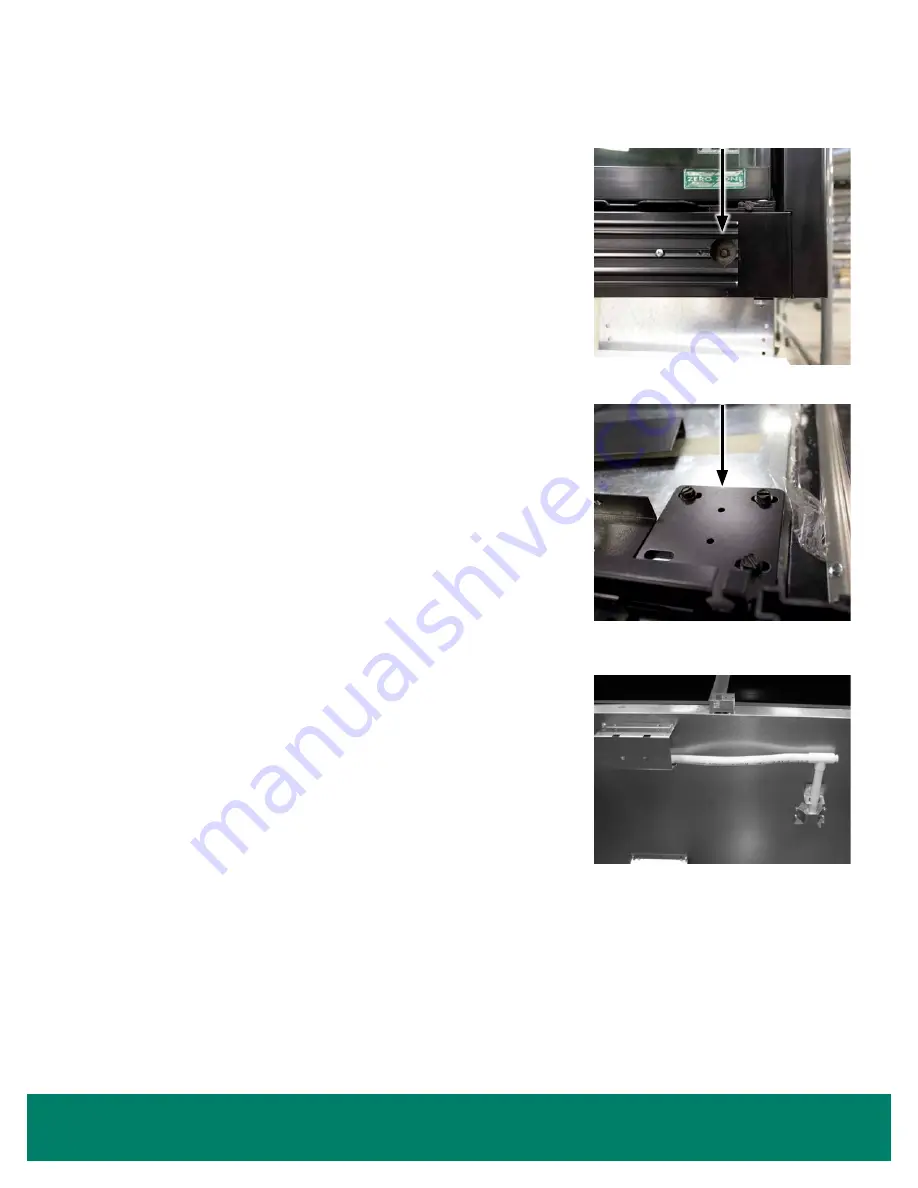
To move the bottom mounting plate, the center locking screw (located behind the bumper)
must be loosened.
1.
To remove the bumper, use a flathead screwdriver to pry it up from the bottom. Lift the
edge, and then slide the screwdriver down the entire length of the bumper to loosen it.
Once the bottom edge is disconnected, use a hammer to tap the screwdriver upwards
and disengage the bumper from the upper track. Remove the bumper.
2. loosen the center locking screw by 2 turns, accessed through the hole in the bumper
). This will allow the bottom mounting plate to shift. Do
not remove the center locking screw.
3. Tap the door’s aluminum extrusion with a rubber mallet to shift the door. Once the door
is in position, retighten the center locking screw.
TOP MOUNTING PLATE
1. To access the top mounting plate, remove the top trim piece. This will require a Phillips
bit and a 1/4" hex screw bit.
2. loosen all 3 screws that secure the slotted plate by 2 turns (
).
Do not remove the screws.
3. Tap the door's aluminum extrusion with a rubber mallet to shift the door. Once the door
is in position, retighten all screws.
Drain
The drain is located at the center of the case in the floor pan. The 1" PVC drain outlet is
located at the center front of the case behind the kickplate.
The drain line exits the case in the center. The lateral runs of drain pipe should be installed
through the bases (
). There is no room in front of the base for the drain pipe
because the kickplate installs directly to the front of the bases.
Install the tee to the outlet pipe and a drain trap to the tee. Plug the open end of the tee
using the clean-out plug supplied with the drain trap kit. The drain line must be pitched
away from the case. The tee, drain trap, and plug are supplied with the case.
The drain
trap must be level. The drain trap should be primed with water after installation.
The
drain line must be pitched away from the case enough to ensure proper drainage. Consult
your local codes for minimum requirements.
Cases with 1" bases are shipped on wooden skids or pallets. The forward drain section,
tee, and “R” trap are shipped loose for field installation.
Condensate Removal System
Zero Zone remote cases can be equipped with a condensate removal system. The system uses a drain pan with pump located behind the
kickplate and a condensate evaporation pan mounted on the top of the case.
Condensate water and any liquid spilled in the case will drain into the drain pan. The pump is equipped with a float that turns the pump on when
there is a sufficient liquid level. Liquid is pumped through a plastic hose through a check valve and into the condensate evaporation pan. The
evaporation pan is equipped with a heater and a float switch to turn on when the heater is submerged in liquid. When the heater is energized,
the evaporation pan will be extremely hot and should not be touched. The pump and evaporation pan should be cleaned regularly. Any spilled
product, other than water, should be cleaned to prevent odors.
FIGURE 21: Center Locking Screw
FIGURE 22: Top Mounting Plate
FIGURE 23: Drain Installation


