10 • General
and
for the typical component layout of the 30" door case.
The kick plate must be removed to gain access to the drain clean out. Disassemble the kick plate by removing the 2 or 3 metal screws located
in the kick rail.
Evaporator
The evaporator coil, located at the rear bottom of the case, is factory-assembled with distributor, expansion valve, and other refrigeration
components. To inspect the coil, remove the center or left of center coil cover. A small inspection window is located at the rear of the case. To
inspect the entire coil, remove the remaining coil covers and raise the evaporator cover.
Expansion Valve
Unless otherwise specified, a superheat adjustable externally equalized thermostatic expansion valve with a removable strainer and pressure
limiting charge is mounted to the evaporator coil. The valve is not preset. Adjust the superheat setting for maximum coil effectiveness. Typical
superheat settings are between 6°F and 10°F. Close coupled systems should use the higher superheat setting to minimize the chance of liquid
flood back. To adjust the expansion valve, remove the right end coil cover. Remove the cap from the bottom of the valve. When looking at the
valve stem end, turn the valve stem counterclockwise to decrease superheat. Turn the valve stem clockwise to increase superheat. Measure
the suction line temperature at the expansion valve sensing bulb and compare it to the suction temperature corresponding to the saturated
pressure. Make sure that line pressure drop is taken into account.
Turn the valve stem only 1/4 turn at a time and allow sufficient time (20 to 30 minutes) for the valve to settle before making any further
adjustments. Replace the valve stem cap after the valve superheat has been adjusted. BE CERTAIN THE VALVE STEM CAP IS WIPED DRY
FIRST.
!
CAUTION!
DISCONNECT POWER TO THE CASE BEFORE SERVICING ELECTRICAL COMPONENTS TO AVOID PERSONAL
INJURY AND DAMAGE TO THE UNIT.
Evaporator Fans
Air is circulated throughout the case with 115 volt fan motors. These motors must be operating at all times except during defrost. Fan motors
should be replaced with motors having the same characteristics including type, physical size, lubricant temperature range, wattage and RPM.
Fan blades should be replaced with OEM parts or have the same fan pitch as the OEM fan blade.
Fan Removal
1. Unplug fan from fan power supply plug located on the front face of the fan housing.
2. Remove the fan blade nut and fan blade.
3. Remove the two mounting bolts and remove the fan assembly from the fan housing.
4. Remove the three fan motor mounting screws from the back of the fan motor.
Reverse steps 1-4 to install.
GENERAL
Summary of Contents for CRYSTAL MERCHANDISER
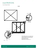
Page 25: ...Illustrations Case Squareness 23 Illustrations Figure 6 Case Squareness Refer back to page 5...
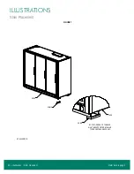
Page 26: ...24 Illustrations Shim Placement Illustrations Figure 7 Shim Placement Refer back to page 5...
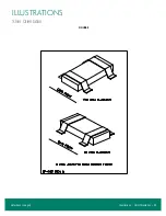
Page 27: ...Illustrations Shim Orientation 25 Illustrations Figure 8 Shim Orientation Refer back to page 5...
Page 29: ...Illustrations Spacer Block 27 Illustrations Figure 10 Spacer Block Refer back to page 6...
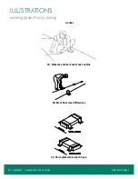
Page 34: ...32 Illustrations Drain Line Illustrations Figure 15 Drain Line Refer back to page 7...
Page 38: ...36 Illustrations Electrical Box Illustrations Figure 19 Electrical Box Refer back to page 11...


