12 • Refrigeration
REFRIGERATION
Piping Penetrations
Unless otherwise specified, the liquid and suction connections are made inside the case under the evaporator fan/coil cover. Refrigerant piping
may enter the case through the left rear back panel or the left rear top panel of the case. The copper pipe should not touch or rub on the edges
of the sheet metal. After connections have been made, the refrigeration access hole in the case must be sealed completely with an aerosol-
dispensed Urethane insulation or equivalent, like Great Stuff
™
, for example. Penetrations made in sheet metal baffles should also be sealed.
Refrigerant Piping
Correct refrigeration line sizing and industry standard installation practices are essential for proper system operation. Zero Zone recommends
that, on a case utilizing top refrigeration exit, the riser be sized to maintain refrigerant velocity and oil return. Refrigeration risers are an available
factory-installed option. Zero Zone recommends one riser per refrigeration circuit on circuits utilizing hot gas defrost. Field piping must be 3"
away from the defrost heater element on cases utilizing electric defrost.
The end frames on the cases have cut-outs built into them to allow for case-to-case field piping, if desired.
Zero Zone recommends a liquid line drier and moisture-indicating sight glass installed on each case prior to the expansion valve, these are also
a factory-installed option.
and
.
Leak Check/Evacuation/Charging
After all of the refrigeration piping and system components have been assembled, the entire system must be pressurized and checked for leaks.
When the system is leak free, evacuate with a deep vacuum pump. Triple evacuation should be done to a minimum of 500 microns and nitrogen
sweep is recommended. After the system has been thoroughly evacuated of all moisture and non-condensable gas, charge the system with the
proper refrigerant, using “hi-side/low-side” charging techniques. Refer online to
GreenChill Leak Check Guidelines
Temperature Settings
R404A FROZEN FOOD
R404A ICE CREAM
Rack Systems
Evaporator Temp -7°F
Rack Systems
Evaporator Temp -16°F
Condensing Unit
Condensing Unit Cut-In 35 psig
Condensing Unit Cut-Out 24 psig
Condensing Unit
Condensing Unit Cut-In 27 psig
Condensing Unit Cut-Out 16 psig
Return & Discharge Air Temperature
Return Air Temp Cut-In 6°F
Return Air Temp Cut-Out 0°F
Discharge Air Temp Cut-In 3°F
Discharge Air Temp Cut-Out -3°F
Return & Discharge Air Temperature
Return Air Temp Cut-In -3°F
Return Air Temp Cut-Out -9°F
Discharge Air Temp Cut-In -6°F
Discharge Air Temp Cut-Out -12°F
Temperature Control
When purchased, factory-installed discharge air sensors are located in the center of the case behind the access panel in the ceiling panel.
There is a sticker installed on the panel that states “sensor located behind.”
If the case is ordered with defrost termination sensors, Zero Zone provides the following sensor locations unless otherwise directed by the
customers’ spec.
1. On cases utilizing hot gas defrost, the sensor is strapped to the dump line.
2. On cases utilizing electric defrost, the sensor is placed in the center of the evaporator coil.
Summary of Contents for CRYSTAL MERCHANDISER
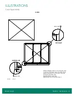
Page 25: ...Illustrations Case Squareness 23 Illustrations Figure 6 Case Squareness Refer back to page 5...
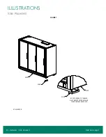
Page 26: ...24 Illustrations Shim Placement Illustrations Figure 7 Shim Placement Refer back to page 5...
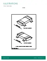
Page 27: ...Illustrations Shim Orientation 25 Illustrations Figure 8 Shim Orientation Refer back to page 5...
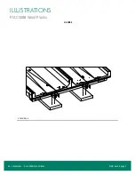
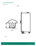
Page 29: ...Illustrations Spacer Block 27 Illustrations Figure 10 Spacer Block Refer back to page 6...
Page 34: ...32 Illustrations Drain Line Illustrations Figure 15 Drain Line Refer back to page 7...
Page 38: ...36 Illustrations Electrical Box Illustrations Figure 19 Electrical Box Refer back to page 11...


