Options - Shroud Frame Assembly • 39
OPTIONS
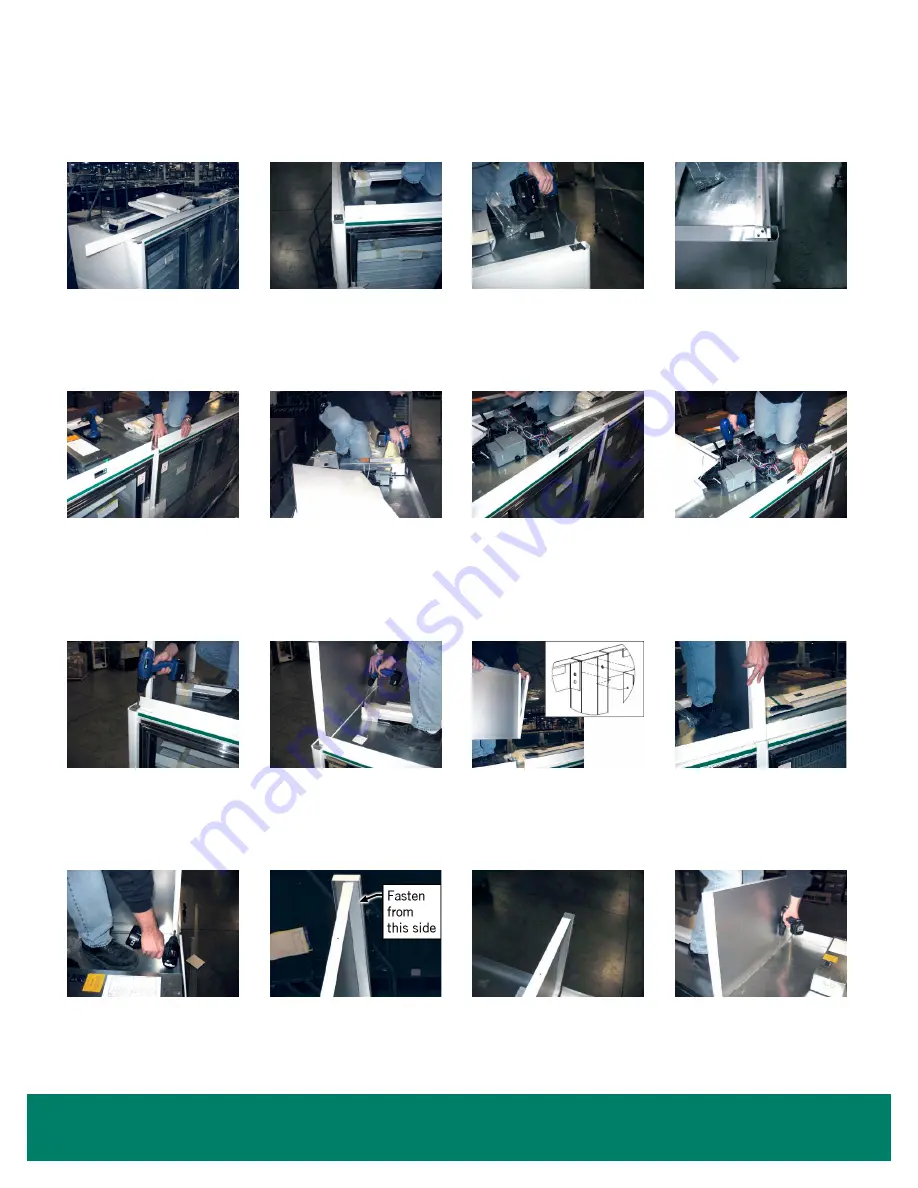
1. Locate the painted lower
shroud of the appropriate
length. (
Note:
Shroud sides
are shipped inside the case.)
2. Working from left to right
(facing the case), position
the lower shroud by placing
it against top Euro trim to the
front and to the edge of the
end panel to the left.
3. Secure with self-tapping
sheet metal screws (three
per piece).
4. Complete.
5. Locate the 2nd painted lower
shroud of the appropriate length
and secure in the same fashion.
In this example, butting up to the
edge of the insulated divider.
(There will be a vertical joint for
the insulated divider.)
6. Remove the cover from the
electrical box and remove
the two screws that secure
the electrical box to the top
of the case.
7. Slide the electrical box into
position making sure that
the Carel Controller display
is clearly visible through the
cutout in the lower shroud.
8. Re-fasten the electrical box
with the same screws you
removed. This procedure will
be duplicated at each case.
9. Remove one of the two screws
from the Euro trim retainer clip
(the screw closest to the case).
10. Locate a shroud side for the
left of the line-up. With the
finished side facing out, line
up the front of the shroud
tight to and even with the
painted lower shroud.
11. At the insulated divider, locate
the insulated divider shroud
piece. Place the shroud side into
the shroud piece. The shroud
piece will act as a cap to the
shroud side.
12. Place the entire assembly
into the gap over the
insulated divider.
13. Using a self-tapping sheet metal
screw, secure the shroud side
to the bottom of the insulated
divider shroud piece. Secure
shroud side to top of case.
14. Note: Edge of shroud side
flange is aligned with edge
of case one.
15. Note: Shroud side over plexi
divider should be installed
as shown.
16. Secure the shroud side with
self-tapping screws making
sure it is square to the front
of the case.
Shroud Frame Assembly


