background image

12  •  Installation & Operation

INSTALLATION & OPERATION
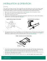
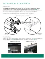
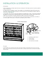
Kickplates

Each case is shipped with a front kickplate. Cases with end panels are shipped with 1 side kickplate per end panel. Cases that join together are 

shipped with a kickplate splice. 

For a standard Reveal

 case (ORMC82) or a Reveal

 Tall case (ORMC87), front and side kickplates are attached to the case bases using 

Tinnerman clips. Position the front kickplate so the flange is on top and facing outward. The screw (supplied) goes through the kickplate and 

into the Tinnerman clip (

See Figure 18

).

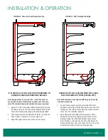
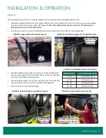
A 2-piece kickplate is used on the Reveal 

 Meat Exclusive (ORMC75-MX and ORMC80-MX) and the Reveal

 Produce Exclusive (ORMC80-PX 

and ORMC82-PX). First, position the lower kickplate flush with the bottom of the bases and fasten it to the bases. Second, position the upper 

kickplate under the case and fasten it to the bases through the lower kickplate. This will create a continuous kickplate.

There is a natural gap between the top of the kickplate and the underside of the Reveal Merchandiser

®

 that allows airflow of 20 CFM/foot. If 

more airflow is required, contact the factory to order optional louvered kickplates (provides 60 CFM/foot).
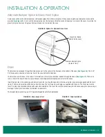
Bumper

Cases are supplied with a protective bumper. Most bumpers will be factory-installed to the bumper support and snap track. If a continuous 

bumper is used, only the bumper support and snap track will be installed. The continuous bumper may need to be trimmed before snapping it 

onto the snap track.

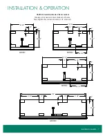
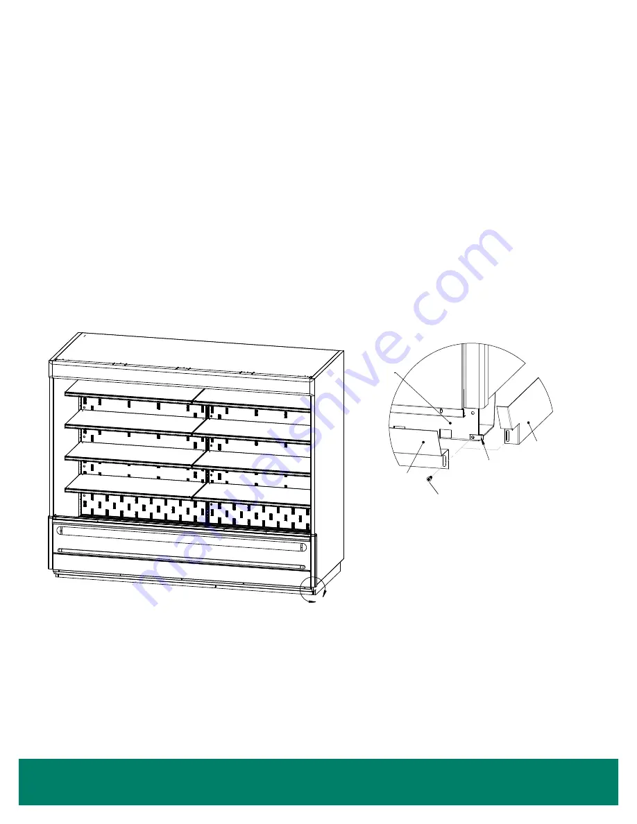
 FIGURE 18: Kickplate Installation

1.  Install Tinnerman clips at each base.
2.  Install side kickplate.
3.  Install front kickplate.
4.  Insert fasteners to secure kickplates.























 












































































































DETAIL A (ASSEMBLED)

4. INSERT FASTENERS TO SECURE KICKPLATES

3. INSTALL KICKPLATE FRONT

1. INSTALL TINNERMAN NUTS AT EACH BASE
2. INSTALL KICKPLATE END

DETAIL A (EXPLODED)

BASE

TINNERMAN NUT

KICKPLATE END

KICKPLATE INSTALLATION

KICKPLATE FRONT

REV.

SP-6108

B

SPECIFIED, ALL DIMENSIONS

(PER SP-0457)


REVEAL

TOLERANCES:

RELEASED

PART WEIGHT:

(IN LBS)

REVISION INFORMATION

B REMOVE EXTRA KICKPLATE COMPONENT FROM DETAIL A.

978

NO MANUAL REVISIONS

CONSENT OF ZERO ZONE, INC. IS STRICTLY PROHIBITED.


CAD DRAWING

REPRODUCTION OR OTHER MEANS, WITHOUT THE WRITTEN 


FINISH:

(PER SP-0404)

(UNLESS OTHERWISE SPECIFIED)

(PER SP-0154)

MATERIAL:

SIZE

NOT TO SCALE

Ron Oman

SCALE:

MODELED BY:

A

ZERO ZONE, INC.

DOCUMENT OR DISCLOSURE OF ITS CONTENTS; BY 

ARE IN DECIMAL INCH

7/27/2016

B

1 OF 1

SP-6108

KICKPLATE ASSEMBLE FIELD

SHEET:

DATE:

REVISION

SHEET

DRAWN BY:

UNLESS OTHERWISE

USA 53153

DRAWING No:

DESCRIPTION:

BY

DATE

ECN No.

REVISION DESCRIPTION

No.

BF

6/9/2020

COPYRIGHT INFORMATION

THIS DRAWING AND THE INFORMATION CONTAINED WITHIN, IS 

THE SOLE PROPERTY OF ZERO ZONE, INC. ANY USE OF THIS 

110 NORTH OAKRIDGE DRIVE

NORTH PRAIRIE, WISCONSIN

David Giese

A

Base

Front 

Kickplate

Side Kickplate

Tinnerman Clip

Fastener

Summary of Contents for Reveal Merchandiser ORMC75-MX

Page 1: ...ZERO ZONE REVEAL MERCHANDISER OPEN MULTI DECKS With ChillBrite LED Lighting INSTALLATION OPERATION MANUAL COMPLIANT 66 0057 REV E Aug 2021...

Page 2: ...Night Curtains 14 Under Shelf Lights 14 Canopy Lights 15 Shelves Stocking Product 15 REFRIGERATION 16 Mechanical Components 16 Evaporator Coil Expansion Valve 16 Evaporator Fans 16 Refrigerant Piping...

Page 3: ...all not be covered by this warranty Extended Warranties In addition to the standard limited warranty for further consideration the Seller will extend to the original purchaser prior to shipment a limi...

Page 4: ...questions or problems arise call Zero Zone at 800 247 4496 Any change to a Zero Zone product made during the installation start up or at any other time must be submitted in writing to Zero Zone for ap...

Page 5: ...Refrigerators and Freezers ANSI Approved equipment certified by NSF NSF 51 Food Equipment Materials ANSI Approved equipment certified by NSF UL 471 Commercial Refrigerators and Freezers ANSI Approved...

Page 6: ...the right end and the second case in the lineup will be labeled on the left end The numbers on each end to be joined will match See Figure 1 The first case in a lineup with the right side labeled x 1...

Page 7: ...instructions CASE MODEL INSTRUCTIONS 4ORMC Forks must extend 20 to 24 under the case from either end 6ORMC Forks must extend 26 to 30 under the case from either end 8ORMC Forks must extend 39 to 43 u...

Page 8: ...not extend beyond the front case bases or they will interfere with installing trim The shims should be oriented to sit under the front and rear bends of each base Tape all shims in place See Figure 7...

Page 9: ...peration 7 Installation Operation Figure 8 Reveal Merchandiser Base Locations 4ORMC 6ORMC 8ORMC 12ORMC Drawings are top views with bases shown under the case Case length does not include end panels 1...

Page 10: ...e setting the next case in the lineup Case caulking instructions and caulk are shipped with every case See Figure 10 on page 9 Move the next case into position and bolt it to the first case using the...

Page 11: ...e to ensure a tight seal 3 Repeat this process between each case in the lineup SURFACES TO BE CAULKED MUST BE CLEAN DRY AND FREE OF FROST ABOVE 40 F Note NSF sealant must be applied with no gaps to se...

Page 12: ...eed to loosen the canopy screws if canopies are not within 3 8 On cases with stainless steel canopies the splice is shipped loose Fit it over both canopies and screw into place Hand Rail Splice Some c...

Page 13: ...s of drain pipe should be installed through the bases See Figure 17 There is no room in front of the base for the drain pipe because the kickplate installs directly to the front of the bases Install t...

Page 14: ...If a continuous bumper is used only the bumper support and snap track will be installed The continuous bumper may need to be trimmed before snapping it onto the snap track Figure 18 Kickplate Installa...

Page 15: ...Install Mirror Support into the Shelf Standards Install into second and third slots from the top Figure 21 Shelf Standard Slots for Air Deflector MIRROR HEIGHT SLOT FOR AIR DEFLECTOR 8 Tall 6th Slot...

Page 16: ...st it until you hear a click as the brackets engage See Figure 24 Once installed the night curtain can be pulled down See Figure 25 Under Shelf Lights 1 Position the under shelf light on the bottom of...

Page 17: ...rack Note Do not place product on the return air grille or past the load limit line Do not exceed shelf load capacity See Figure 28 Do not stand on the case when stocking or adjusting shelves SHELF T...

Page 18: ...hould be replaced with OEM parts or have the same fan pitch as the OEM fan blade CAUTION DISCONNECT POWER TO THE CASE BEFORE SERVICING ELECTRICAL COMPONENTS TO AVOID PERSONAL INJURY AND DAMAGE TO THE...

Page 19: ...valent feet 90 F Liquid 2 F Pressure Drop Up to 150 equivalent feet 90 F Liquid 2 F Pressure Drop Up to 150 equivalent feet 90 F Liquid 2 F Pressure Drop It may be necessary to make adjustments to com...

Page 20: ...rost may cause premature defrost termination Case Thermometer The cases are shipped with two thermometers One thermometer is factory mounted in the center ceiling pocket cover to sense the discharge a...

Page 21: ...case wiring See Figure 37 Terminal blocks are provided for supplying power for fans and lights A ground connection can also be made inside the electrical enclosure Optional top electrical will be loca...

Page 22: ...a mild detergent and warm water or a mild sanitizer 6 If the case is equipped with a condensate pan and pump the drain should be blocked before washing coils Water can be removed with a shop vacuum 7...

Page 23: ...cal Resources page at WWW ZERO ZONE COM or contact the Zero Zone Service Department at 800 247 4496 All specifications subject to change without notice 66 0057 REV E ZERO ZONE INC 800 247 4496 ZERO ZO...

Reviews: