16 • Refrigeration
REfRIgERATION
Mechanical Components
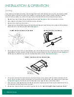
EVAPORATOR COIL & EXPANSION VALVE
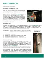
The evaporator coil is located in the bottom of the case under the deck pans. The
thermostatic expansion valve (TXV) is typically located at the end of the evaporator
coil. The TXV is not preset, and superheat should be adjusted to 6-8°F. Contact
Zero Zone for superheat setting if using high-glide refrigerants.
To adjust the TXV, remove the far right deck pan (
from the bottom of the TXV. When looking at the valve stem end, turn the valve
stem counterclockwise to decrease superheat. Turn the valve stem clockwise to
increase superheat. Measure the suction line temperature at the TXV sensing bulb
and compare it to the suction temperature corresponding to the saturated pressure.
Make sure that line pressure drop is taken into account. Turn the valve stem only
1/4 turn at a time and allow sufficient time (20 to 30 minutes) for the TXV to settle
before making further adjustments. After the superheat has been adjusted, wipe the
valve stem cap dry and screw it back on.
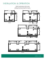
EVAPORATOR FANS
Air is circulated through the display case by fans, which are located below the deck pans in the bottom of the case (
). Air is drawn
through the front return air grill and discharged out of the honeycomb at the top. The fan motors must be operating at all times. Fan motors
should be replaced with motors having the same characteristics including type, physical size, lubricant temperature range, wattage, and RPM.
Fan blades should be replaced with OEM parts or have the same fan pitch as the OEM fan blade.
!
CAUTION!
DISCONNECT POWER TO THE CASE BEFORE SERVICINg ELECTRICAL
COMPONENTS TO AVOID PERSONAL INJuRY AND DAMAgE TO THE uNIT.
1. Disconnect power to the fan.
2. Remove the fan blade nut and fan blade.
3. Remove the mounting bolts and remove the fan assembly from the fan housing.
4. Remove the fan motor mounting screws from the back of the fan motor.
5. Replace the fan, and reverse steps 1-3 to install the cover. Restore case power.
Refrigerant Piping
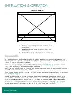
Unless otherwise specified, the liquid and suction connections terminate inside the case under the coil
cover. Refrigerant piping may enter the case through the left rear back panel or the left rear top panel of
the case. Other exit options are available. The copper pipe should not touch or rub on the edges of the
sheet metal. Correct refrigeration line sizing and industry standard installation practices are essential for
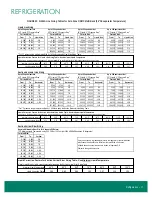
proper system operation (
).
After connections have been made, the refrigeration access holes or penetrations in the case must be
sealed completely with an aerosol-dispensed urethane insulation or equivalent (example: great Stuff).
After all of the refrigeration piping and system components have been assembled, the entire system must
be pressurized and checked for leaks. When the system is leak free, evacuate with a deep vacuum pump.
Triple evacuation should be done to 500 microns or less, and nitrogen sweep is recommended. After the
system has been thoroughly evacuated of all moisture and non-condensable gas, charge the system with
the specified refrigerant.
REfRIgERATION
FIGURE 30: Expansion Valve and Schrader Valve
FIGURE 31: Fans and
Case-to-Case Piping

