


Refrigeration • 17
REfRIgERATION
From
To
Liquid Line
From
To
Liquid Line
From
To
Liquid Line
From
To
Liquid Line
5,280
30,720
3/8
5,280
21,010
3/8
5,280
16,790
3/8
5,280
14,310
3/8
30,730
72,750
1/2
21,020
49,900
1/2
16,800
39,960
1/2
14,320
34,110
1/2
72,760 136,380
5/8
49,910
93,740
5/8
39,970
75,160
5/8
34,120
64,210
5/8
136,390 226,300
3/4
93,750 155,790
3/4
75,170 125,030
3/4
64,220 106,890
3/4
155,800 246,590
7/8
125,040 198,070
7/8
106,900 169,440
7/8
From
To
Horizontal
From
To
Horizontal
From
To
Horizontal
From
To
Horizontal
5,280
8,350
1/2
5,280
5,730
1/2
---
---
---
---
---
---
8,360
15,640
5/8
5,740
10,760
5/8
5,280
8,630
5/8
5,280
7,380
5/8
15,650
25,950
3/4
10,770
17,880
3/4
8,640
14,360
3/4
7,390
12,280
3/4
25,960
41,010
7/8
17,890
28,290
7/8
14,370
22,740
7/8
12,290
19,460
7/8
41,020
82,770
1-1/8
28,300
57,220
1-1/8
22,750
46,030
1-1/8
19,470
39,430
1-1/8
82,780 143,860
1-3/8
57,230
95,580
1-3/8
46,040
80,190
1-3/8
39,440
68,720
1-3/8
143,870 226,880
1-5/8
95,590 157,230
1-5/8
80,200 126,700
1-5/8
68,730 108,640
1-5/8
157,240 325,130
2-1/8
126,710 262,250
2-1/8
108,650 225,030
2-1/8
From
To
Vertical
5,280
6,590
5/8
6,600
10,500
3/4
10,510
21,300
7/8
21,310
37,300
1-1/8
37,310
59,100
1-3/8
59,110 121,880
1-5/8
121,890 215,800
2-1/8
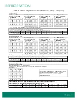
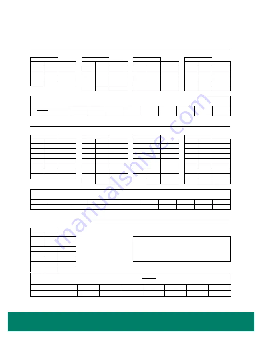
90°F Liquid, 2°F Pressure Drop
‡
Up to 50 equivalent feet
‡
For 1°F pressure drop, multiply rated Btuh by 1.44 before using the Suction Horizontal Line Sizing Table.
∆
For 1°F pressure drop, multiply rated Btuh by 1.45 before using the Liquid Line Sizing Table.
Suction Vertical Riser Sizing
Up to 100 equivalent feet
Up to 50 equivalent feet
90°F Liquid, 2°F Pressure Drop
∆
Up to 100 equivalent feet
Up to 200 equivalent feet
90°F Liquid, 2°F Pressure Drop
∆
Liquid Line Sizing
Suction Horizontal Line Sizing
90°F Liquid, 2°F Pressure Drop
‡
Up to 200 equivalent feet
90°F Liquid, 2°F Pressure Drop
‡
Up to 150 equivalent feet
90°F Liquid, 2°F Pressure Drop
‡
Up to 150 equivalent feet
90°F Liquid, 2°F Pressure Drop
∆
It may be necessary to make adjustments to compensate for special situations
which cause the actual Btuh to differ from the rated Btuh of the cases.
All liquid line and suction line sizes are inches, refrigeration O.D.
Subject to change without notice.
70°F Minimum Liquid Temperature, using 0.35 PSI Per 100 Feet (per 2006 ASHRAE Handbook - Refrigeration)
For rated Btuh:
Maximum Allowable Riser Size For Adequate Oil Return*
R-404 Line Sizing Tables for Zero Zone OVMC Multideck (+26°F Evaporator Temperature)
For rated Btuh:
For rated Btuh:
For rated Btuh:
For rated Btuh:
For rated Btuh:
For rated Btuh:
For rated Btuh:
For rated Btuh:
90°F Liquid, 2°F Pressure Drop
∆
Liquid Correction Factors for Suction Vertical Riser Sizing Table - Use Minimum Liquid Temperature
Multiply rated Btuh by liquid correction factor before using the Suction Vertical Riser Sizing Table
40°F
50°F
60°F
70°F
80°F
90°F
100°F
0.85
0.89
0.94
1.00
1.07
1.15
1.24
Minimum Liquid Temperature:
Liquid Correction Factor:
40°F
50°F
60°F
70°F
80°F
90°F
100°F
120°F
0.74
0.78
0.82
0.87
0.93
1.00
1.08
1.32
1.19
Liquid Correction Factors for Suction Horizontal Line Sizing Table - Use Maximum Liquid Temperature
For max imum liquid temperatures other than 90°F, multiply rated Btuh by liquid correction factor before using the Suction Horizontal Line Sizing Table
Max imum Liquid Temperature:
110°F
Liquid Correction Factor:
40°F
50°F
60°F
70°F
80°F
90°F
100°F
120°F
0.98
0.97
0.96
0.97
0.98
1.00
1.04
1.17
Liquid Correction Factors for Liquid Line Sizing Table - Use Maximum Liquid Temperature
For maximum liquid temperatures other than 90°F, multiply rated Btuh by liquid correction factor before using the Liquid Line Sizing Table
Max imum Liquid Temperature:
110°F
Liquid Correction Factor:
1.09
FIGURE 32: R-404A Line Sizing Tables for Zero Zone ORMC Multi-Deck (26°F Evaporator Temperature)