background image

10  •  Installation & Operation

INSTALLATION & OpERATION

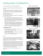
Door Leveling (Door Sag/Sawtooth)

Doors must be leveled before the bumper and kickplate are installed (

See 

Figure 10

).

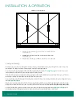
For French-swing doors, there should be a 7/16" gap between doors at the 

handle side and a 3/8" at the hinge side. To set the proper gaps, loosen the 

screws holding the top or bottom door mounting plates, then shift the door.

BOTTOM MOUNTING PLATE

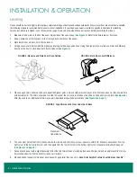
To move the bottom mounting plate, the center locking screw (located behind 

the bumper) must be loosened.

1. 

 To remove the bumper, use a flathead screwdriver to pry it up from the 

bottom. Lift the edge, and then slide the screwdriver down the entire 

length of the bumper to loosen it. Once the bottom edge is disconnected, 

use a hammer to tap the screwdriver upwards and disengage the bumper 

from the upper track. Remove the bumper.

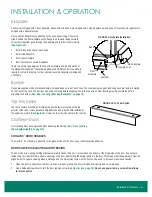
2.   Loosen the center locking screw by 2 turns, accessed through the hole 

in the bumper support plate (

See Figure 11

). This will allow the bottom 

mounting plate to shift. Do not remove the center locking screw.

3.  Tap the door’s aluminum extrusion with a rubber mallet to shift the door. 

Once the door is in position, retighten the center locking screw.

TOP MOUNTING PLATE

1.  To access the top mounting plate, remove the top trim piece. This will 

require a Phillips bit and a 1/4" hex screw bit.

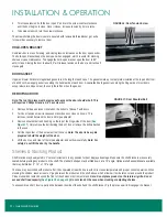
2.  Loosen all 3 screws that secure the slotted plate by 2 turns (

See Figure 

12

). Do not remove the screws.

3.  Tap the door's aluminum extrusion with a rubber mallet to shift the door. 

Once the door is in position, retighten all screws.

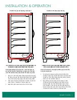
Drain

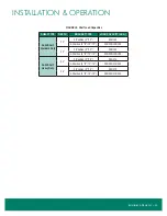
The 1.5" PVC drain line exits from the bottom center of the case. The lateral 

runs of drain pipe should be installed through the bases, as needed (

See 

Figure 13

). There is no room in front of the base for the drain pipe because the 

kickplate installs directly to the front of the bases.

Install the drain tee to the outlet pipe and a drain trap to the tee. Plug the open 

end of the tee using the clean-out plug supplied with the drain trap kit. The 

drain line must be pitched away from the case. The tee, drain trap, and plug 

are supplied with the case. The drain trap must be level. The drain trap should 

be primed with water after installation. The drain line must be pitched away 

from the case enough to ensure proper drainage, typically at least 1/4" per foot. 

Consult your local codes for minimum requirements.

The forward drain section, tee, and “R” trap are shipped loose for field 

installation.

 FIGURE 10: Properly Leveled Doors

7/16" Gap on 

Handle Side

3/8" Gap on 

Hinge Side

 FIGURE 11: Center Locking Screw

 FIGURE 12: Top Mounting Plate

 FIGURE 13: Drain Installation

Summary of Contents for Reveal Merchandiser ORMC83D

Page 1: ...ZERO ZONE REVEAL MERCHANDISER MULTI DECKS WITH DOORS With CoolView Ultra Doors ChillBrite LED Lighting INSTALLATION OPERATION MANUAL COMPLIANT 66 0109 REV C May 2021...

Page 2: ...op Mounting Plate 10 Drain 10 Kickplates 11 Bumper 11 Top Trim Splice 11 CoolView Doors 11 CoolArc Door Handles 11 Door Closer Adjusting Door Tension 11 Hold Open Bracket 12 Door Gasket 12 Removing a...

Page 3: ...rther consideration the Seller will extend to the original purchaser prior to shipment a limited extended warranty on the compressor only following expiration of the standard warranty The Seller agree...

Page 4: ...frigeration technicians If any questions or problems arise call Zero Zone at 800 247 4496 Any change to a Zero Zone product made during the installation start up or at any other time must be submitted...

Page 5: ...d Freezers ANSI Approved equipment certified by ETL ASHRAE Standard 72 Method of Testing Commercial Refrigerators and Freezers ANSI Approved AHRI 1200 Performance Rating of Commercial Refrigerated Dis...

Page 6: ...Every case in a lineup has a packet attached to the shelving that contains important information about the case and or lineup and if applicable special instructions for installing ordered options Bump...

Page 7: ...anels Do not place them under the bumper support or drain pipe as that will crush the components Cases have steel protective support plates under the end panels not under insulated dividers to protect...

Page 8: ...ch base to equal the highest point Shims should not extend beyond the front case bases or they will interfere with installing trim The shims should be oriented to sit under the front and rear bends of...

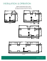
Page 9: ...peration 7 Installation Operation Figure 6 Reveal Merchandiser Base Locations 4ORMC 6ORMC 8ORMC 12ORMC Drawings are top views with bases shown under the case Case length does not include end panels 1...

Page 10: ...with Butyl caulk before setting the next case in the lineup Case caulking instructions and caulk are shipped with every case See Figure 8 on page 9 Move the next case into position and bolt it to the...

Page 11: ...e to ensure a tight seal 3 Repeat this process between each case in the lineup SURFACES TO BE CAULKED MUST BE CLEAN DRY AND FREE OF FROST ABOVE 40 F Note NSF sealant must be applied with no gaps to se...

Page 12: ...ccess the top mounting plate remove the top trim piece This will require a Phillips bit and a 1 4 hex screw bit 2 Loosen all 3 screws that secure the slotted plate by 2 turns See Figure 12 Do not remo...

Page 13: ...he spring tension to the door This means that the square pin must be aligned with the square opening when installing a door An adjustment screw on the front can be used to increase or decrease tension...

Page 14: ...oes not close on its own This removes tension between the door and torque adjuster 3 Remove shoulder bolt and bushing on the top of the hinge side of the door See Figure 17 Only remove the bolt holdin...

Page 15: ...Duty 22 2 Position 0 10 250 150 4 Position 0 5 10 15 250 250 150 100 24 2 Position 0 10 250 150 4 Position 0 5 10 15 250 250 150 100 Solid Shelf Heavy Duty 22 2 Position 0 10 350 275 4 Position 0 5 1...

Page 16: ...ided inside the case on the right hand side of the coil for venting and draining the system Refrigerant Piping Correct refrigeration line sizing and industry standard installation practices are essent...

Page 17: ...Refrigeration 15 Refrigeration Figure 21 R 404A Line Sizing Tables for Zero Zone Cooler 28 F Evaporator Temperature...

Page 18: ...uct location as required by NSF Specific field installation instructions are packaged with the NSF thermometer SETTING ORMC83D ORMC88D Evap Temp 28 F 28 F Condensing Unit Cut In 74 psig 74 psig Conden...

Page 19: ...diagram with off cycle defrost Note Always refer to the wiring diagram shipped with the case Optional top electrical will be located in a junction box on top of the case External wiring should be size...

Page 20: ...nd warm water or a mild sanitizer 6 If the case is equipped with a condensate pan and pump the drain should be blocked before washing coils Water can be removed with a shop vacuum 7 Coils may be clean...

Page 21: ...2021 Zero Zone Inc All Rights Reserved May 2021 For other technical support please refer to the Technical Resources page at WWW ZERO ZONE COM or contact the Zero Zone Service Department at 800 247 44...

Reviews:

Related manuals for Reveal Merchandiser ORMC83D