
12 • Installation & Operation
INSTALLATION & OpERATION
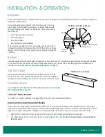
3. To increase tension, hold the door open 2" and turn the screw counter-clockwise
until the door begins to close. Once it closes, increase tension by 2 more turns.
4. To decrease tension, turn the screw clockwise.
The screws holding the door closer are secured with removable threadlocker gel; extra
force will be necessary to remove them.
HOLD-OPEN BRACKET
CoolView
®
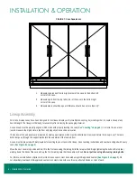
doors are self-closing, and closing tension increases as the door opens wider.
The hold-open bracket keeps the door open when engaged, which is useful for stocking
shelves or case maintenance. To engage the hold-open bracket, open the door to 90°
until it clicks. Closing the door to about 80° will release tension on the door, and it will self
close again.
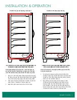
DOOR GASKET
Upper and lower horizontal magnetized gaskets run the length of each case. The gaskets mate up to steel plates installed at the top and bottom
of each door. a sweeper gasket runs along the handle-side of each door. a specialized bulb gasket runs along the hinge-side of most doors,
except where two hinges meet, then only the left door has the gasket.
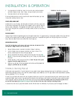
REMOVING A DOOR
Note: The top trim piece must be removed to access the door shoulder bolt. This
will require a Phillips bit and a 1/4" hex screw bit.
1. Remove hold-open bracket, located on the bottom of Reveal
™
with doors.
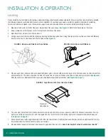
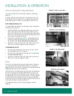
2. Turn door tension screw clockwise until door does not close on its own. This
removes tension between the door and torque adjuster.
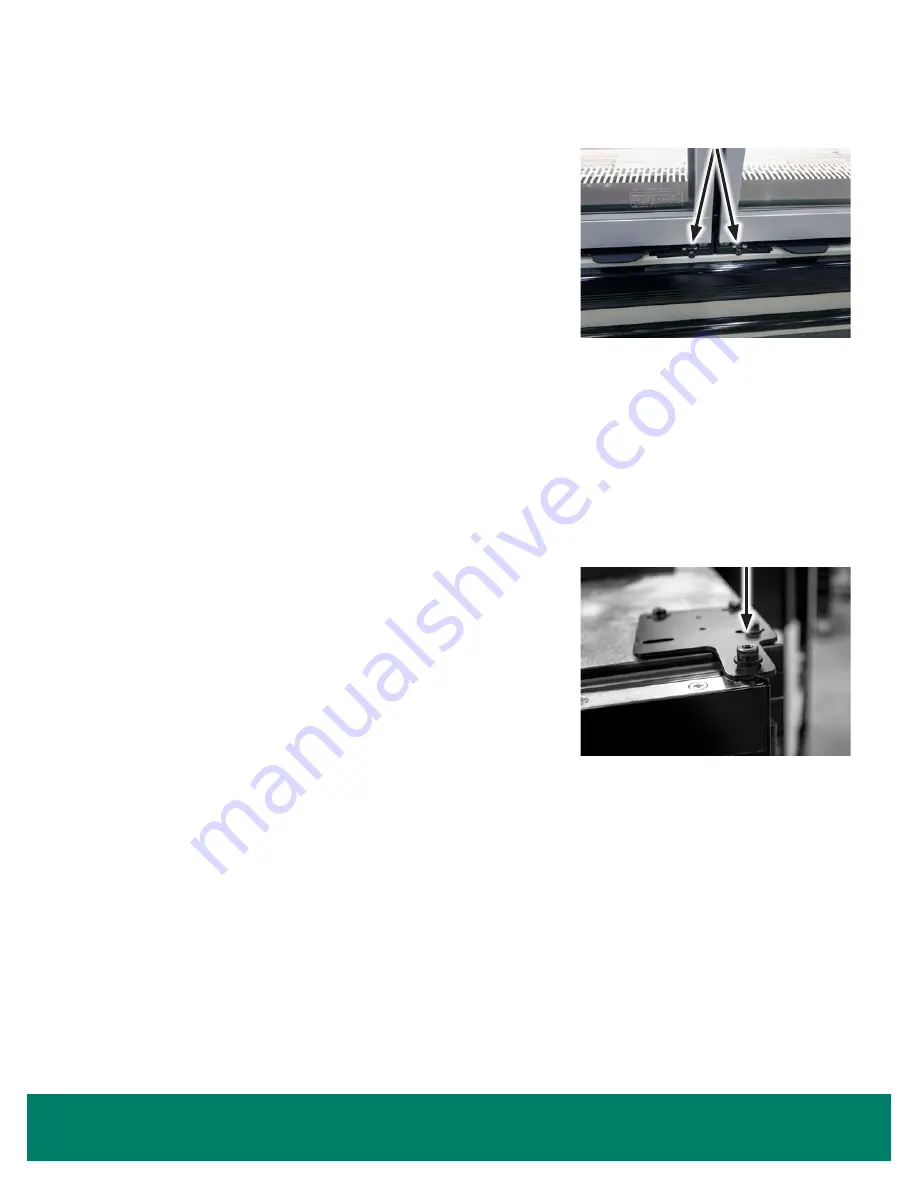
3. Remove shoulder bolt and bushing on the top of the hinge-side of the door (
). Only remove the bolt holding the door; do not remove the bolts attached
to the case.
4. Pull the top corner of the door away from the case. Note: The door is heavy. Be
prepared to hold the weight of the door.
5. Lift the door up and clear of the torque adjuster and set down carefully. Note: For
safety, do not lift the door by the handle.
Shelves & Stocking Product
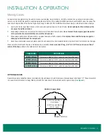
Shelf location may be adjusted in 1" vertical increments in any position for best display advantage. Make sure the shelf brackets are securely
seated before placing any product on the shelf. The standard shelves may be tilted down at a 10° angle. Optional shelf assemblies are available
that may be tilted at 5°, 10°, or 15° angle.
The case may be stocked with product after it has operated at least 24 hours with correct case temperature and proper control operation. When
stocking the shelves, leave at least a 1" gap between the product and the shelf above, which allows air to circulate over and around the product.
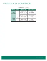
Product should not extend beyond the front of the shelves or bottom wire rack. Note: Do not place product on the return air grille. Do not
exceed shelf load capacity (
). Do not stand on the case when stocking or adjusting shelves.
To unassemble a shelf, insert a putty knife between the side of the shelf and the shelf bracket. Pry the pieces apart to disengage the bracket.
FIGURE 17: Door Shoulder Bolt
FIGURE 16: Door Tension Screw