Electrical • 17
ELECTRICAL
ELECTRICAL
General
!
CAUTION!
DISCONNECT POWER TO THE CaSE BEFORE SERVICING ELECTRICaL COMPONENTS TO aVOID PERSONaL
INJURy aND DaMaGE TO THE UNIT.
Cases will have 2 electrical circuits for the fan circuit and the lighting circuit.
The electrical enclosure is located behind the lower trim on the right side of
the case. The enclosure includes the power connection and power supplies
for the LED light sticks. The light switch is located on the front right side of the
). When supplying electrical power to the case,
connect to the supplied black and white wires and wire nuts inside the electrical
enclosure. a ground connection should also be connected inside the electrical
enclosure.
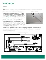
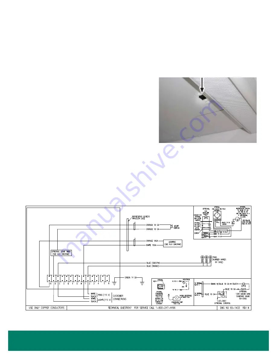
for typical wiring diagram with off-cycle defrost.
Note: Always refer to the wiring diagram shipped with the case.
Optional top electrical will be located in a junction box on top of the case.
External wiring should be sized according to the amperage rating stamped on
the serial tag, which is located on the ceiling inside the left-hand door. Typical
electrical values are shown on specification sheets that are available online. All
internal wiring has been completed at the factory.
all wiring must comply with the National Electrical Code (NEC) and all local codes. after installing the equipment, correct operation of the
electrical circuits, controls, and defrost controls should be verified. All operating voltages and amperages should be measured and recorded.
In coolers, 1 sensor bulb is factory installed. Temperature probe wires are white (common) and green (supply). The temperature probe
(discharge air) is located in the false ceiling.
FIGURE 25: Sample Wiring Diagram
FIGURE 24: Light Switch

