
4 • Installation & Operation
INSTALLATION & OpERATION
INSTALLATION & OpERATION
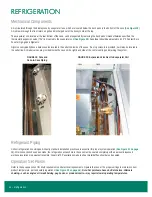
Delivery Inspection
Zero Zone display cases are carefully factory-tested, inspected, and properly packed to ensure delivery in the best possible condition. The
equipment should be unwrapped and checked for damage immediately upon delivery. DAMAGE MUST BE NOTED AT TIME OF DELIVERY,
AND ALL CLAIMS FOR DAMAGES MUST BE FILED WITH THE TRANSPORTATION COMPANY, NOT WITH ZERO ZONE. The carrier will
supply necessary report and claim forms.
Do not leave, store, or hold case outdoors in direct sunlight or high ambient temperature. With the end panels on, the case is airtight;
the inside temperature of the case will increase, and the heat will be unable to escape. This could potentially cause any plastic inside
the case to deform or warp.
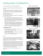
Packaging
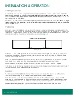
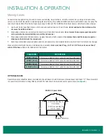
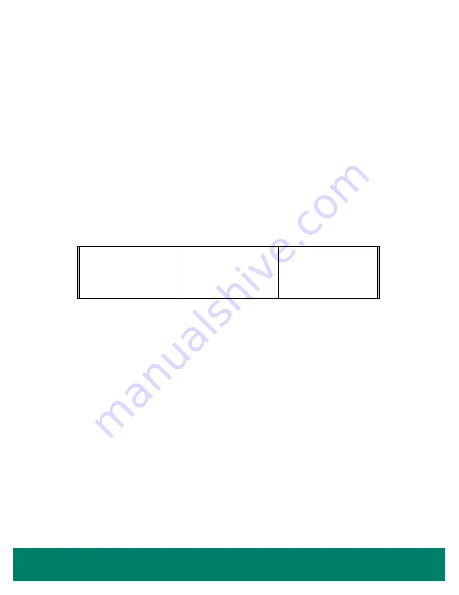
Each case in a lineup is labeled to identify the lineup and joint. The label uses a two digit number designation, separated by a decimal. The
first number indicates the case lineup. The second number indicates the case joint. Case joints begin with the number “1” at the left most joint in
the lineup when looking at the front of the lineup. The first case in the lineup will be labeled on the right end and the second case in the lineup
will be labeled on the left end. The numbers on each end to be joined will match (
The
first
case in a lineup (with the right side labeled “x.1”) has a packet attached to the shelving that contains touch-up paint. Every case in
a lineup has a packet attached to the shelving that contains important information about the case and/or lineup and, if applicable, special
instructions for installing ordered options.
Bumpers and kickplates are shipped on top of the case. Shelves for the case are tie-wrapped and blocked into the individual cases. Other
accessories like drain traps, drain pans, and condensate evaporation pans are shipped in the cases that require the parts.
Materials for joining cases—including caulk, joining bolts, splices, and end filler posts—are shipped in each case to be joined.
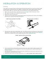
The doors are prevented from opening during shipment with the use of door-holding shipping brackets. The brackets are screwed to the top of
the case at each door and should be removed when the case is unpacked.
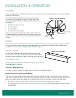
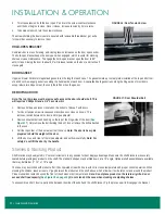
Location
Zero Zone cases must not be installed in the direct rays of the sun or near a source of radiant heat. Be certain that the floor under the
installation is of sufficient strength to prevent sagging. Uneven surfaces will result in reduced performance.
Cases should be set to allow a minimum 3" of space behind the back of the units. This will allow necessary air to circulate behind the
display cases and prevent condensation. Higher humidity stores with minimal air circulation require at least a 4" gap. a minimum 2" gap is
recommended between cases on end-to-end installations. all minimum spacing requirements may increase if seismic restraints are used.
Building soffits must be set back at least 6" from the front of the case to allow access to electrical wiring on the top of the case.
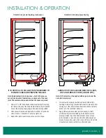
Front of Back-to-Back Lineup
1.1B 1.1B
1.2B 1.2B
1.1a 1.1a
1.2a 1.2a
Front of Lineup
1.1 1.1
1.2 1.2
FIGURE 1: Case Label Information
Front of Lineup