background image

Page 4 

 
OPERATING INSTRUCTIONS FOR COOLER 


It is important to read through these instructions carefully before operating the cooler. 
 
This instruction manual should be kept in a safe place for future reference. 
 

GAS THERMOSTAT OPERATION 


USER OPERATING INSTRUCTIONS 
 
Note: Appliance cannot be run off 2 heat sources at the same time. 
 
TO START GAS OPERATION 

 
1.  Open the shut-off valve for the gas bottle (check that there is enough gas). 
 

Open any shut-off valve of the gas installation. 

 
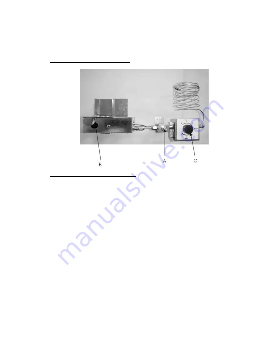
2.  Open flap B. 
 
3.  Keep the flame failure device knob (A) pressed in for approximately 15 seconds. 
 
4.  Release for 10 seconds, strike match and insert into flap hole.  Press (A) again. 
 
5.  Keep the knob (A) pressed in for a further 15 seconds then release it.  If the flame 
 

goes out, repeat steps 2, 3 and 4 until the flame stays alight. 

 
To terminate the gas operation turn off the shut-off valve on the gas bottle. 
 
On starting the cooler, it will take a few hours to start becoming cold. 


  Once  the  burner  (B)  has  been  lit  turn  the  gas  thermostat  (C)  to  position  ‘7’  for 

maximum cooling (clockwise).


  By  adjusting  the  thermostat  (C)  knob  down  from  position  ‘7’  you  can  regulate  the 

temperature you desire in the bottle cooler.


NOTE:

  The gas safety valve knob (A) should never be depressed for periods longer than  

15 seconds with the burner unlit, as this can cause a potentially dangerous build-
up  of  unburnt  gas.  If  the  burner  does  not  ignite,  allow  sufficient  time  for  any 
unburnt gas to disperse, then repeat the ignition steps. 


Summary of Contents for GR250BC

Page 1: ...INSTRUCTIONS ZERO MODEL GR250BC L P Gas Double Lid Bottle Cooler ZERO APPLIANCES PTY LTD Cat I3 28 30 37 I3B P 30 WARNING THIS APPLIANCE MUST BE EARTHED ENSURE THAT THE GAS SUPPLY HOSE IS NOT IN CONTA...

Page 2: ...pane mixtures at 3 0 kPa Declared Rate Injector size 0 42mm diameter marked 13 or 0 Gas consumption 34 2 g h Electrical Supply optional 230V 0 320kW WARNING THIS APPLIANCE MUST BE EARTHED ENSURE THAT...

Page 3: ...be installed in accordance with the requirements of SANS 10087 1 and any fire department regulations and or local bylaws applicable to the area If in doubt check with the relevant authority before und...

Page 4: ...n 15 seconds see Users note BURN BACK FIRE IN BURNER TUBE OR CHAMBER In the event of a burn back where the flame burns back to the jet immediately turn off the gas supply at the control valve on the p...

Page 5: ...e Press A again 5 Keep the knob A pressed in for a further 15 seconds then release it If the flame goes out repeat steps 2 3 and 4 until the flame stays alight To terminate the gas operation turn off...

Page 6: ...l is defective 7 The baffle has not been inserted into the chimney factory fitted 8 The absorption unit is leaking A leak can be determined in the case of a visible leak by traces of yellow deposit at...

Page 7: ...hich the lid is opened and the volume and concentration of products stored in it 10 You avoid packing products in too tightly air must be able to circulate freely 11 For the safety of children keep th...

Page 8: ...w used for admitting the ammonia hydrogen filling charge to an absorption unit is fitted to the unit s reservoir It is a strictly applied provision of the guarantee extended on the unit to the custome...

Page 9: ...burner will not stay alight check position of the flame detector head and the functioning of the safety valve If not cold enough Check through points listed under Troubleshooting In the unlikely event...

Page 10: ...SUPPLY HOSE IS NOT IN CONTACT WITH OR NEAR THE BURNER BOX 1 SANS BRASS HOSE TAIL 2 GAS THERMOSTAT 3 CAPILLARY WIRE 4 FLAME FAILURE DEVICE 5 M10 NUTS 6 M10 x 3 8 UNF JET HOLDER 7 M10 x 1 JET RETAINER...

Page 11: ...Made in South Africa Pty Ltd...

Page 12: ......

Reviews: