background image

zero

HOME AUTOMATION

Z02 - SWING GATE

PG3

INDEX

01. 

SAFETY INSTRUCTIONS

02. OPERATOR


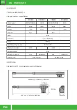
TECHNICAL SPECIFICATIONS 

 DIMENSIONS


03. INSTALLATION


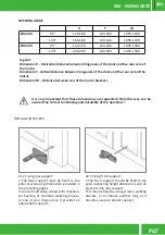
INSTALLATION DIMENSIONS 


INSTALLATION STEPS 


TYPICAL INSTALLATION


04. MAINTENANCE


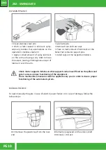
MANUEL RELEASE

05. TROUBLESHOOTING

01. SAFETY INSTRUCTIONS

ATTENTION:

•To ensure the safety of people, it is important that you read all the following instructions. 

Incorrect installation or incorrect use of the product can cause physical injury and material 

damage.

•Keep these instructions in a safe place for future reference.

•This product was designed and produced strictly for the use indicated in this manual. Any 

other use, not expressly indicated here, could compromise the good condition/ operation of 

the product and/or be a source of danger.

•ZERO SRLS. is not responsible for the improper use of the product, or other use than that 

for which it was designed.

•ZERO SRLS. is not responsible if safety standards were not  taken into account when instal

-

ling the equipment, or for any deformation that may occur to it.

•ZERO SRLS. is not responsible for the safety and proper operation when using components 

not sold by them.

•Do not make any modifications to the operator components and / or their accessories.

•Before installation unplug the automatism from the source of power.

•The installer must inform the client how to handle the product in case of emergency and 

provide this manual to user.

•Keep remote controls away from children, to prevent the automated system from being 

activated involuntarily.

•The customer shall not, under any circumstances, attempt to repair or tune the operator 

.Must call qualified technician only.

•Connect the automatism to a 230V plug with ground wire.

•Operator for outdoor and indoor use.

Summary of Contents for Z02 Series

Page 1: ...zero HOME AUTOMATION Z02 SWING GATE PG1 USER MANUAL AND CONFIGURATION Z02 REV01 2018 IT EN FR zero HOME AUTOMATION Z02 SWING GATE MOTOR SUPPLY 230 24V...

Page 2: ...zero HOME AUTOMATION Z02 SWING GATE PG2 zero HOME AUTOMATION...

Page 3: ...RO SRLS is not responsible for the improper use of the product or other use than that for which it was designed ZERO SRLS is not responsible if safety standards were not taken into account when instal...

Page 4: ...re the following Z02 400 Z02 400 24 Z02 600 Z02 600 24 Power Supply 230Vac 50 60Hz 24Vdc 230Vac 50 60Hz 24Vdc Power 180W 60W 180W 60W Current 1 4 A 1 3 A 1 4 A 1 3 A Capacitor 8 F 8 F RPM 1400 Noise l...

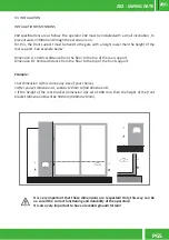
Page 5: ...from the floor to the top of the rear support Dimension B Vertical distance from the floor to the top of the front support Example Set dimension A this can be any size of your choice After you set di...

Page 6: ...ening mechanical stopper On the Illustrated diagrams below and are the dimensions for the installation of the automated system Opening mechanical stopper Opening direction EXTERIOR Axis of rotation of...

Page 7: ...r support must be fixed to the pillar or wall using dimensions provided in the preceding pages It can be fixed using screws with mechani cal bushing or chemical welding process or one of your choice s...

Page 8: ...rlier on each place with a small amount of lubricant for less friction Move the door manually to see if the door opens and closes uniformly and cor rectly without any irregular friction during its ent...

Page 9: ...nt to use mechanical stoppers in the opening and closing position of the gate If not respected components of the automation may suffer efforts for which they were not prepared and as a result will be...

Page 10: ...omogeneous layer of lubricant over the arm Lubricate pins Remove front and rear caps Place a small amount of lubricant on the holes that contains support pins Install caps on the respective holders 04...

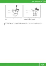
Page 11: ...SWING GATE PG11 02 Insert Release key on the unlock shaft 03 Rotate key 180 in the direction indi cated in the figure to unlock NOTE To lock operator so it can work automatically must do it by turnin...

Page 12: ...n t close Unlock motor and move the gate by hand to closed position Lock motor again and turn off power supply for 5 se conds Reconnect it and send start signal using transmitter Gate opened but didn...

Page 13: ...ere is some security systems malfunction photocells safety edges etc 1 Close with a shunt all safety systems on the control board check manual of the control board in question If the automated system...

Page 14: ...____________________________________________________ _____________________________________________________________________ _____________________________________________________________________ _______...

Page 15: ...zero HOME AUTOMATION Z02 SWING GATE PG15 zero HOME AUTOMATION...

Page 16: ...zero HOME AUTOMATION Z02 SWING GATE PG16 zero HOME AUTOMATION ZERO SRLS Via ROMA 25 A ALTAVILLA VIC ITALIA info miozero it www miozero it...

Reviews: