background image

2. How to set up a Zero Wire DMX system - Page 4


2.


How to set up a Zero Wire DMX system 

The Zero Wire DMX system is shipped containing the following components: 


2 Zero Wire DMX boxes 


2 Mains Cables 


Manual & Configuration Software CD 


RS232 Programming Cable 


Overview: 


Zero Wire DMX Box: A device that takes in USITT DMX 512 and converts the data 
into IP (Internet Protocol) packets embedded within Ethernet Frames for delivery 
across a wireless Ethernet system. 

One box is configured to act as an encoder and one as a decoder. To enable the system to 
work from the box the following steps need to be followed: 


Connect the box labelled as the encoder to the lighting console. 


Connect the box labelled as the decoder to the lighting fixtures. 


Power up the boxes. 

The system will now allow the transfer of DMX data from the encoder to the decoder. If the 
system seems to be underperforming it might be due to interference from another wireless 
network. To overcome this it may be necessary to switch to another wireless channel, or use 
a WAP (Wireless Access Point) box. Please refer to section 3 for information on using a WAP 
and switching channels. 

Working with the Boxes 


The boxes are designed to be the entry and exit points for data transmitted over the 
network.  


A wireless network as a single entity can support up to 250 boxes.  


It is possible for each box to be set to either encode or decode data. 


One encoder can talk to 249 decoders on a single network. 


4 encoders can talk to 60 decoders each all on the same wireless network. 


It is possible to extend the system beyond 4 universes by adding more WAPs to 
create further wireless networks. 

Specification 


Mains voltage inlet connector: allows for mains power supply in the range of 
90-260 v(AC). 


5 Pin XLR Input– allows the box to act as an encoder. 


5 Pin XLR Output – allows the box to act as a decoder. 


RS232 port – allows for the box to be configured by connecting it to any 
computer with an RS232 9 pin Serial port, or via USB with the appropriate 
converter. 


3 stack Red LED indicator – allows for analysis of system operation. Provide 
indication of termination, data receive or transmit rate, and system status. 


Mode Green LED indicator – shows if box is set to encode or decode mode. 


Terminator Switch – allows for termination of the DMX run, when the box is in 
encode mode and is in line after some DMX devices that require termination. 


For shipping, the boxes are preconfigured as one encoder and one decoder, in ad-hoc mode, 
allowing immediate use. If ordered with a WAP, the boxes will be configured to work in 
infrastructure mode, talking through the WAP. 

If the boxes are to be used on a larger network or in conjunction with another system, or to 
extend the size of an existing system then they must be reconfigured accordingly. 

Summary of Contents for Zero Wire DMX

Page 1: ...ro 88 Usk House Llantarnam Park Cwmbran Gwent NP44 3HD UK www zero88 com Tel 44 0 1633 838088 Fax 44 0 1633 867880 Email sales zero88 com Stock No 73 776 00 IM8352 Iss 01 Zero Wire DMX Operators Manua...

Page 2: ...4 A NOTE ON OTHER WIRELESS NETWORKS 10 5 RUNNING A SHOW 10 6 SYSTEM CONFIGURATION OPTIONS 11 Simple point to point AdHoc 11 Simple point to point Infrastructure 11 Simple point to multi point Infrastr...

Page 3: ...countries across the world users must familiarise themselves with the available local frequencies and work within local regulations Wireless Ethernet 802 11 systems can cause interference to and rece...

Page 4: ...ngle entity can support up to 250 boxes It is possible for each box to be set to either encode or decode data One encoder can talk to 249 decoders on a single network 4 encoders can talk to 60 decoder...

Page 5: ...ro Wire Configuration Utility can be started Select the COM port which the Zero Wire box has been connected to or press Search Now that a COM port has been selected you can press Read Config to read t...

Page 6: ...ection 3 for information on WAP channel allocation SSID This is the Wireless networks SSID or name it must be the same as the WAP and all other Boxes on the same network for every device to function a...

Page 7: ...to every decoder on the same network If you only wanted the encoder to send the DMX data to one specific decoder then you would enter the IP address of that specific decoder Unless there are special c...

Page 8: ...on the same SSID will move channels So if you experience data corruption or interference whilst using the Zero Wire DMX system you can instantly move to a clear channel This ability to change channel...

Page 9: ...channels Although channels 1 and 2 are numerically different the physical frequencies which they represent overlap Depending on which other wireless networks are in use in the local area you may need...

Page 10: ...lexibility at show time it is recommended that a wireless networked enabled laptop is present and running both the WAP configuration software and the latest version of Net Stumbler This allows for ide...

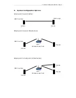
Page 11: ...mple point to point AdHoc Simple point to point Infrastructure Simple point to multi point Infrastructure Decode r Encode r Decode r DMX From Desk DMX to Light Encoder Decoder WAP Wireless Access Poin...

Page 12: ...ure Decode r CAT5 Cable Link Ethernet From Desk LeapFrog 48 96 or Frog2 Encoder Decoder WAP Wireless Access Point DMX From Desk DMX to Lights Universe 1 Universe 2 Universe 3 Universe 4 Universe 1 Uni...

Page 13: ...AP s using the Internet Encoder Decoder WAP Wireless Access Points DMX from Desk DMX to Lights Universe 1 Universe 2 Universe 3 Universe 4 Universe 1 Universe 1 Universe 2 Universe 3 Universe 4 Encode...

Page 14: ...d by or under the supervision of an appropriately qualified or trained person E OE Zero 88 is a trading style of Cooper Controls Ltd Zero 88 2007 All third party trade marks acknowledged For news view...

Reviews: