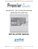
PREMIER QUATRO INSTALLATION MANUAL (Fyreye MKII) Firmware Versions: PANEL 1.84 & LOOP 3.70
Doc No: GLT-215-7-1 Issue: 1.36 Author: NJ/TE DATE: 25/05/2017
12
3.5 INDICATING DIFFERENT PANEL STATES
During Normal operation the panel will be in one of the following states depending on the status of the devices connected to the
panel, and user intervention. Below is a summary of the different conditions
3.5.1 The Quiescent Condition
This is the panels’ normal state. There are no faults or alarms, and the panel is running normally. This is indicated by The LCD
showing System Normal, and All LEDS being off, apart from Power, and perhaps Controls Active (depending on the position of the
key switch.
In the quiescent condition, the panel displays:-
Panel/site name (if entered), Time & date, System Normal Message, and Zeta
MKII Panel for a Fyreye MKII Protocol system.
Note: The number of loop cards are installed inside the panel will be reflected
on the System Normal message.
3.5.2 The Alarm Condition
A fire is indicated on the Quatro panel by the COMMON FIRE red LED (A steady LED represents a Call Point Alarm, and a flashing
LED represents a Detector Alarm). The zonal location of the fire is indicated by one of the zonal indication red LEDs. Zonal indication
is limited to the first 20 (or 120 with a 100 Zone LED expansion card) zones of the installation. Fires in all zones will be indicated on
the LCD. An example of the 4 line fire display is shown below:
First Zone in Alarm
Line 1 indicates the first zone in fire. In the example, the first alarm was in Zone
3. Zone 3 is the Second Floor.
The 2nd line indicates the most recent zone in fire. The format is the same as line
1. The most recent fire occurred in Zone 5, which is the Fourth Floor.
FIRST ALARM: Z003 - SECOND FLOOR
LAST ALARM : Z005 - FOURTH FLOOR
ZONES IN FIRE:004 POINTS IN FIRE:010
PRESS ◄ OR ► TO SCROLL
Two or more zones in alarm
Line 1 indicates the first zone in fire. In the example, the first alarm was in Zone
3. Zone 3 is the Second Floor.
The 2nd line indicates the most recent zone in fire. The format is the same as line
1. The most recent fire occurred in Zone 5, which is the Fourth Floor.
Line 3 shows the total number of zones in fire and the total number of points /
devices in fire.
FIRST ALARM: Z003 - SECOND FLOOR
LAST ALARM : Z005 - FOURTH FLOOR
ZONES IN FIRE:004 POINTS IN FIRE:010
PRESS ◄ OR ► TO SCROLL
All the points that are in the fire condition can be displayed in turn by using the
◄
or
►
keys to scroll through the fires. This
information is displayed on lines 3 and 4. For example:
In this example, line 3 indicates the 2nd point of the 10 points in fire. Point 2 was
triggered at the time 08:10. Point 2 is in Zone 17 (the Stair Well). Point 2 is an
Optical detector connected to Panel 2 and Loop 4. Its address is 124.
FIRST ALARM: Z003 - SECOND FLOOR
LAST ALARM : Z005 - FOURTH FLOOR
002/010-08:10 Z017 – STAIR WELL
MKII-AOP (2.4.124)- ROOM 101
Note that if the device in alarm is connected to one of the loops of the panel which is indicating the fire, the panel number is not
displayed in line 4, i.e. MKII-AOP (4.124 - ROOM 101).
Panel/site name 10/12/13 13:30
SYSTEM NORMAL
ZETA MARKII 4 LOOP PANEL
www.acornfiresecurity.com
www.acornfiresecurity.com

