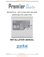
PREMIER QUATRO INSTALLATION MANUAL (Fyreye MKII) Firmware Versions: PANEL 1.84 & LOOP 3.70
Doc No: GLT-215-7-1 Issue: 1.36 Author: NJ/TE DATE: 25/05/2017
13
3.5.3 The Fault Condition
All faults are indicated by a flashing yellow common fault LED, and either an additional fault LED, or an LCD message.
Faults can be divided into 2 types, “Faults” and “Device Faults”. Device Faults are any fault associated with a particular address on
the loop. Faults are everything else, e.g. sounder circuits, power supply etc. Any fault on the panel will flash the common fault LED
in addition to displaying details of the fault. Some examples are shown below:-
In this example, the MKII-AOH detector at loop 1 address 6 had been removed
It is shown as the first fault on the system (Fault 0001/0001), and the time &
date of the event are logged.
FAULT 0001/0001 10/12/13 13:51
MKII-AOH (1.006) REMOVED
TEXT : Reception Opposite Stairway
In this example, there is a short circuit fault on the on board sounder circuit two.
FAULT 0001/0001 10/12/13 13:51
Short Fault SOUNDER TWO
3.5.4. Disablement
To aid commissioning and assist routine maintenance checks, various functions of the Quatro fire alarm system can be disabled as
described in the disablements section later in the manual.
Disablements are indicated with the general disablement LED, and a mixture of LCD/LED indications. Examples are:-
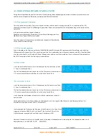
In this example, zone 1 is disabled. It is the only disablement (001/001). Zone 1
fault/test/disable LED and the general disablement LEDs are lit steady
10/12/13 13:51
DISABLED ZONES 001/001
Z001 – Ground Floor
[ - ] [ + ]
In this example, the addressable point at loop 1 address 1 is disabled. It is a call
point. General disablement LED is lit. Zone is not lit because the whole zone is
not disabled
10/12/13 13:51
DISABLED POINTS 001/001
MCP (1.001) Front Door
[ - ] [ + ]
In this example, sounder circuit 1 on the motherboard has been disabled
10/12/13 13:51
DISABLED PCB SOUNDER 001/001
SOUNDER ONE
[ - ] [ + ]
3.5.5. Test Mode
To aid commissioning and assist routine maintenance check, a non-latching ‘one man test’ facility is available.
When a detector, manual call point or input unit is triggered on any zone in Test, the Alarm sounders operate for approximately 10
seconds on and then switch off. The triggered device is automatically reset. The panel will enter the fire condition and indicate the
address of the fire. The panel automatically resets from the fire condition at the same time as the triggered device, but the LCD
indication remains until the panel is manually reset.
If the device is still in the fire condition, e.g. MCP still activated or the analogue value of a detector still above the alarm threshold,
the device will be triggered again and the Alarm sounders will operate for a further 10 seconds.
If an Alarm occurs on a zone that is not programmed to test, the Fire Alarm Panel will continue to operate as normal.
In this example, zone 1 is in test mode. It is the only zone in test mode
(001/001). Zone 1 fault/test/disable LED and the general test LEDs are lit
and are steady.
10/12/13 13:51
ZONES IN TEST 001/001
Z001 – Ground Floor
[ - ] [ + ]
www.acornfiresecurity.com
www.acornfiresecurity.com

