PREMIER QUATRO INSTALLATION MANUAL (Fyreye MKII) Firmware Versions: PANEL 1.84 & LOOP 3.70
Doc No: GLT-215-7-1 Issue: 1.36 Author: NJ/TE DATE: 25/05/2017
44
10- MENU COMMAND STRUCTURE
This section summarises the complete command structure of the Quatro panel. Various functions can be accessed at different
levels within the panel, the
NO ACCESS
level, the
CONTROLS ACTIVE
level, the
USER
level, and the
INSTALLER
level.
At the
NO ACCESS
level (where the black controls key is switched OFF), the basic status of the panel is indicated by its LEDs and
alphanumeric display (LCD). An overview of any fires fault, disablement and test condition can all observed at this level. An audible
warning is also given when a new event occurs. With one exception all the keys (i.e. front door buttons) are inactive at this level.
The exception occurs when a delay to the fire alarm outputs (sounders etc.) has been selected by the installation engineer. In this
case, when a fire alarm is indicated,
[END DELAY]
is displayed above key
F4
. Pressing
F4
causes the outputs to be activated
immediately.
At the
CONTROLS ACTIVE
level, the following controls are active:
START/STOP SOUNDERS, SILENCE BUZZER, RESET, the
►
and
◄
keys to scroll faults and fires, the F keys to display faults during a
fire alarm and scroll between information on the main screen during disablements and test conditions, and the numeric keys to
change a password.
At the
USER
level, the user can also access the information shown below in Section 18.1, by entering his / her unique level 1
password
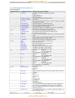
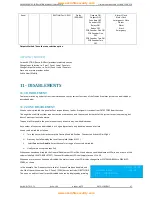
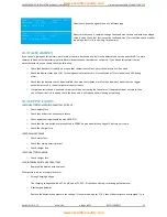
10.1 USER LEVEL (LEVEL 1)
Default Password 1111
PRIMARY SELECTION
SECONDARY SELECTION
COMMENT
Zones
Show
Displays zone details
Show En. Zones
Indicates enabled zones
Show Dis. Zones
Indicates disabled zones
Show Test Zones
Displays zones in test mode
Enable
Enables zones in range x to y
Disable
Disables zones in range x to y
Test
Zones in range x to y are changed to test mode & enables / disables
sounders in zones in test mode
Point
Show
Shows loop, address, zone, type, mode, analogue value, text for each point
Show Dis. Points
Indicates disabled points
Enable
Enables points in range x to y
Disable
Disables points in range x to y
Relays
Enable All
Enables
all relays
Disable All
Disables
all relays
Enable by Zone
Enables relays in zones x to y
Disable by Zone
Disables relays in zones x to y
PCB outputs
Enable / Disable Alarm relay and /or Fault relay on Terminations PCB
Show
Shows the number of Enabled & Disabled Relays
Sounders
Enable All
Enables all sounders
Disable All
Disables all sounders
Enable by Zone
Enables sounder by zone (or range of zones)
Disable by Zone
Disables sounder by zone (or range of zones)
PCB outputs
Enable / Disable PCB sounder 1 and/or 2
Show
Shows the number of Sounders
Logs
Faults
Event No Date/Time
Event Panel No/Loop No/Addr
Zone (if applicable) Text (if applicable)
Alarms
Event No Date/Time
Event Panel No/Loop No/Addr
Zone (if applicable) Text (if applicable)
Test
Event No Date/Time
Event Panel No/Loop No/Addr
Zone (if applicable) Text (if applicable)
All
Event No Date/Time
Event Panel No/Loop No/Addr
Zone (if applicable) Text (if applicable)
Delays
Delay On/Off
Switches delay on/off which has been selected at AL3
Test LED & LCD
All LEDs and LCD pixels active. Buzzer activated
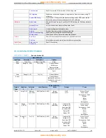
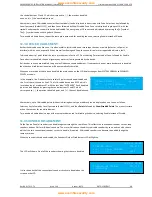
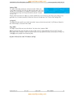
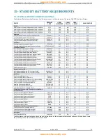
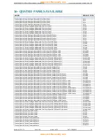
The installation engineer has to access the information in Section 10.2 by entering the unique level 2 password.
www.acornfiresecurity.com
www.acornfiresecurity.com

