INFINITY ID2 INSTALLATION MANUAL.
Software Versions: PANEL 1.N & LOOP O.N
Approved Document No: GLT-211-7-1
Issue 1.9 Author: MG/NJ Date: 06/04/2016
PAGE 7
5 DESIGNING A SYSTEM
This manual is not designed to teach Fire Alarm System design. It is assumed that the System has been
designed by a competent person, and that the installer has an understanding of Fire Alarm System components
and their use.
We strongly recommend consultation with a suitably qualified, competent person regarding the design of the Fire
Alarm System. The System must be commissioned and serviced in accordance with our instructions and the
relevant National Standards. Contact the Fire Officer concerned with the property at an early stage in case he
has any special requirements. If in doubt, read BS 5839: Pt 1: 2013 “Fire Detection and Alarm Systems for
buildings (Code of Practice for System Design, Installation, commissioning and maintenance)” available from the
BSI, or at your local reference library.
5.1 Designing a ID2 System
Designing a ID2 System is a fairly straight forward matter. It just takes a bit of thought to zone allocation during
the system design stage.
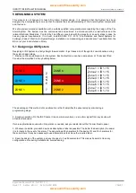
1. Decide on the zone allocation for the system. Each default zone can have a maximum of 15 devices fitted.
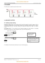
Consider the simplified 3-storey building below.
The advantage of this method of zone allocation is that it simplifies the panel setup by eliminating a
programming stage.
2. Sounder operation. On the ID2 Panels, it is a common sounders, i.e. an alarm signal from any device will
activate all sounders.
If more sophisticated sounder & I/O operation is needed, ask your dealer about the Premier Quatro panel.
3. Whenever possible, give each device as descriptive a label as possible. The better the description, the easier
it is to locate in the event of an alarm. The panel allows 20 characters for the device ID, and 16 characters for
the zone labels. It may be necessary to use abbreviations to achieve the required label.
4. Keep the design of the system, and any changes to it well documented. This makes it easier to trace any
configuration errors during installation & commissioning.
Zone 1 = ID 1-15
Zone 2 = ID 1-15
Zone 3 = ID 1-15
Zone 4 = ID 1-15
Zone 5 = ID 1-15
Zone 6 = ID 1-15
Zone 7 = ID 1-15
Zone 8 = ID 1-14
Z
O
N
E
7
ZONE 5
ZONE 6
ZONE 1
ZONE 2
ZONE 3
ZONE 4


