INFINITY ID2 INSTALLATION MANUAL.
Software Versions: PANEL 1.N & LOOP O.N
Approved Document No: GLT-211-7-1
Issue 1.9 Author: MG/NJ Date: 06/04/2016
PAGE 31
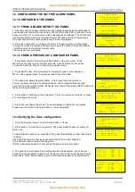
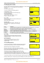
15.2 Viewing device status
On the ID2, all Zone devices can be viewed from the Main Menu, or viewed & edited from Engineer Menu 1.
Enter Engineer menu 1 as described above, and select option 1
(ID Device)
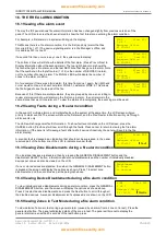
The following screen is shown
The screen is divided into the following sections:-
Configured Device Type
This shows the Device that was at this address during
the last loop configuration.
The possibilities for this are:-
Optical, Ion, Heat, Call-Pt, Sounder, I/O Unit,
Zone Mon, SndSmoke , SndHeat.
Device Status
This is the current status of the device. It will show one of
the following values:-
Normal, Fault, Alarm or Prealarm
Fault Description
If the device is in a fault condition, a description of the
fault will appear here. It will show one of the following
messages:-
FAULT
MEANING
Changed
The device had been changed with one of a different type since last configuration. The message
will flash between Changed, and the new type of device seen (eg. Heat).
Missing
The device is not communicating (ie removed , damaged or Address setting changed)
DetRmvd
A Detector has been removed (from an ID2 Base only)
Side A Only
There is a break in the cable, and the device is only seen from Side A – Loop Mode Only
Side B Only
There is a break in the cable, and the device is only seen from Side B – Loop Mode Only
2-ADDR
Two devices have the same ID switch setting
No message
This device is signalling an internal fault by returning a value of less than 8.
Device Label
This is the 20 character description of the device location
entered by the installer. To change this Press Enter button
to activate the cursor.
Device Identification
This is the Zone and address of the device. This is
how the device will probably be referred to on the
system drawings.
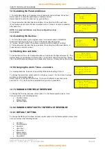
15.3 Locating a device
From the ID device screen, it is possible to send commands to individual
devices to start their sounder, or to turn on their alarm LED / Flasher.
Select the Zone and ID for the device to be checked.
If the device has an LED,, its LED can be turned on by pressing
Button 4. A star will appear in the top right hand corner to show that the LED has
been lit on this device. Press again to turn off.
If the device is a sounder or I/O with a relay, the sounder or relay
can be started by pressing the GENERAL TEST button. The Outline
sounder Symbol turns solid to show that the Sounder is active. Press again to turn off.
Similarly their Flasher can be started by pressing button 4. Press 4 again to turn off.
The sounder and flasher can both be activated if required. (Press General test, then 4)
Scrolling to another device or exiting the menu will automatically turn the LED or sounder/flasher off.
Call-Pt
Normal
Front Door
Zone:01ID:04
Call-Pt
Normal
Front Door
Zone:01 ID:04
Call-Pt
Normal
Front Door
Zone:01ID:04
Optical
Missing
FAULT
Fl 3 Bedroom 303
Zone:01ID:05
Optical
Normal
Fl 3 Bedroom 303
Zone:01ID:05
Optical
Normal
Fl 3 Bedroom 303
Zone:01ID:05
Optical
Analog: 25 Normal
Fl 3 Bedroom 303
Zone:01ID:05
Optical
*
Normal
Fl 3 Bedroom 303
Zone:01ID:05


