background image

ZEC-DOC-USER-MANUAL-MIZ-21C (180 - 1030496 - 1 - A) - 1  

Page 3 

1.


Safety Precautions and Symbols 

This section contains the most important precautions to follow, and identifies and explains the 
various safety symbols found on the instrument. Before turning on the instrument, make sure that 
these safety precautions are taken, as described below. 

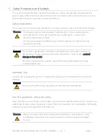
Safety Indications 

The purpose of the various safety indications is to ensure operator safety and instrument integrity. 

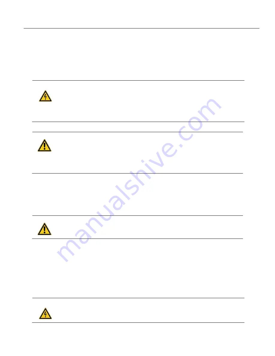
W

ARNING


The Warning sign denotes a hazard. It calls attention to a procedure, practice, 
or the like, which, if not correctly performed or adhered to, could result in 
severe personal injury or death. 
Do not proceed beyond a Warning sign until the indicated conditions are fully 
understood and met. 


C

AUTION


The Caution sign denotes a hazard. It calls attention to a procedure, practice, or 
the like, which, if not correctly performed or adhered to, could result in 

material 

damage or loss of data.


Do not proceed beyond a Caution sign until the indicated conditions are fully 
understood and met. 


Intended Use 

The MIZ-21C is designed to perform nondestructive inspections on industrial and commercial 
materials. 

C

AUTION


Do not use the MIZ-21C for any purpose other than the intended use.  


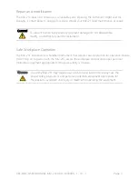
Use of equipment and accessories 

Zetec provides a series of eddy current probes and accessories that allow the MIZ-21C to perform a 
wide range of eddy current inspections. Contact Zetec with questions on compatibility of third party 
products to ensure safe operation of the MIZ-21C. 
 

W

ARNING


Always use equipment and accessories that meet 

Zetec’s

 specifications. Using 

incompatible equipment could cause malfunction and/or equipment damage, 
or injury. 


Summary of Contents for MIZ-21C

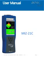
Page 1: ...ZEC DOC USER MANUAL MIZ 21C 180 1030496 1 A 1 Page 1 User Manual MIZ 21C...

Page 2: ...ublication may not be reproduced in any form without permission of Zetec Inc MIZ Air LockTM Zetec THE INSPECTION ADVANTAGE and WAVE design are trademarks or registered trademarks of Zetec Inc in the U...

Page 3: ...nd met CAUTION The Caution sign denotes a hazard It calls attention to a procedure practice or the like which if not correctly performed or adhered to could result in material damage or loss of data D...

Page 4: ...mpt to repair the instrument Safe Workplace Operation The MIZ 21C instrument is a handheld instrument that requires user interaction for operation Before performing an inspection with the MIZ 21C secu...

Page 5: ...pose than the stated intended use Only use cables and accessories approved by ZETEC for this instrument MIZ 21C shall only be connected to the supplied power adapter and cables for charging and or ope...

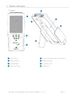
Page 6: ...MANUAL MIZ 21C 180 1030496 1 A 1 Page 6 2 Features and Layout Features Power Button Control Buttons System Display Connector Panel Product Information and Serial Number Instrument Stand Protection Cov...

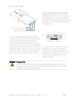
Page 7: ...supplied with the MIZ 21C The charging port can be used to recharge the internal batteries as well as powering the instrument for longer term operation or when the battery level is lower than is requi...

Page 8: ...l references may be provided on features not included on your specific model Compare the model information tag on the back of the MIZ 21C with the following table to understand your exact features Con...

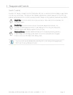
Page 9: ...Tap on most screens allows you to select a menu item or move features on the data screen Double Tap is used on select screens to provide deeper functionality For example double tapping on the C Scan d...

Page 10: ...Movement provides up down left right movement of the active screen item along with select button in center Holding the select button is also used to capture a screenshot Function Buttons corresponding...

Page 11: ...om this menu choice Selecting a menu choice can be performed by the touch screen method or through the control buttons Touch Screen Control Button Directly select the menu item on the screen Move the...

Page 12: ...ssist the user in the review of data Depending on the application type in use the MIZ 21C will either display a 2D or 3D type of screen Application Type 2D 3D Bolt Holes Conductivity and Coating Thick...

Page 13: ...tatus Wi Fi and Bluetooth status are also present for units where this feature is available The main title area displays the current technique name in use When edits have been applied to the saved tec...

Page 14: ...displays the calibration contextual menu Underlay Tool in 2D mode displays menu to capture and display a reference Lissajous signal under the active data in Sub Surface Techniques Filter displays the...

Page 15: ...e adjustment or buttons for fine adjustment The context menu at the bottom of the screen will be active during phase adjustment and clicking the Done button will save the changes Phase is a function o...

Page 16: ...control buttons Context Menu Navigation Touch Screen Control Button Directly select the menu item on the screen Select by function button directly below the screen option Data Display Area 2D Data Dis...

Page 17: ...ing Down the Instrument Press and hold the power button for 2 seconds to power down the MIZ 21C Selecting an Application Once the MIZ 21C is fully powered up the initial display will show the various...

Page 18: ...the right arrow on the keypad Default techniques are locked however a copy can be made from any technique and modified for use The Copy button in the Context Menu allows for copying and naming a new...

Page 19: ...e name at the top of the screen to note the technique is not saved A modified technique can be saved at any time by selecting Save from the context menu in the editing screen If the technique is curre...

Page 20: ...Calibrate menu mode The Calibrate mode provides tools to adjust settings such as scale and rotation The lower portion of the display shows the Data Buffer see page 16 for selecting a data segment for...

Page 21: ...pts when used Length Unit Sets the unit of measure for linear references Coating Thickness Unit Sets the unit of measurement for conductivity shim thickness settings displayed values for coating thick...

Page 22: ...without the need for external equipment The Standard Diagnostics and Surface Array Diagnostics require the addition of a hardware load plug which places an impedance load on the system to test a great...

Page 23: ...us and Information This option provides a report of current version numbers of the operating system MIZ 21C software MIZ 21C firmware and MIZ 21C FPGA program In addition the current runtime of the sy...

Page 24: ...ement option in the Tools section Saving files to USB The destination for Data files and screenshots can be configured by selecting Save File option on the tools menu Selecting this option will presen...

Page 25: ...provides the basics of operation Zetec offers training videos to provide advanced information on setup and use of the MIZ 21C instruments to help users become proficient in operation of the MIZ 21C P...

Page 26: ...to install batteries with correct polarity direction as shown in the illustration The MIZ 21C has polarity direction icons molded into the housing as shown in the inset as a reminder of the correct p...

Page 27: ...Z 21C SF 2 MIZ 21C 2 MIZ 21C ARRAY 32 Frequency Range 5 Hz to 10 MHz Generator Output Up to 19 Vpp Injection Modes Continuous and Super Multiplex Receiver Gain 10 53 dB 43 dB range Data Resolution 16...

Page 28: ...RESENTATION EITHER IMPLIED OR EXPRESSED WITH RESPECT TO QUALITY PERFORMANCE NON INFRINGEMENT MERCHANTABILITY OR FITNESS FOR A PARTICULAR PURPOSE This device includes Windows 10 IoT Core software licen...

Reviews: