5
Operational Option Links A, B, C, D & E
Important:
The functions set by links A, B and C can all be configured via a PC communications
link (RS232) using the Command Console Interface. It is strongly advised that this method is
used rather than physically changing links as damage may occur during disassembly and
subsequent reassembly.
Inside the cylindrical pressure housing there are 3 (on the 2 digit counter) or 5 (on the 4 digit
counter) links on the front interface PCB nearest to the display (which can be seen through the
window of the 2 digit counter).
These links allow the user to change the operation of the display controls (A, B, C) if it is not
possible to connect the system to a PC RS232 port, and to adjust the display brightness of the 4
digit or dual 4 digit counter (D, E).
Note: The link positions can be overridden through the console interface, and vice versa. i.e.
fitting or removing links A, B or C will swap the current enabled or disabled state of the control,
to the alternate state.
Factory default link setting is A, B, C & E fitted.
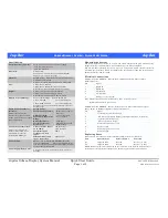
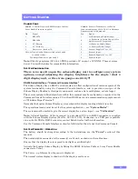
Display Brightness / Typical Battery Life All Digits Continuously Illuminated With
Average Number of segments lit
Link D Link E Brightness
4 digit / Days
Dual 4 digit / Days
Off
Off
Low
9
4.5
On
Off
Medium Low
6
3
Off
On
Medium High (Default)
4
2
On
On
High
3
1.5
Note: At lower brightness level settings, inconsistencies in display segment brightness may
become apparent due to tolerances in their design and manufacture. If your application requires
the increased battery life offered by lower display brightness, please contact Zetechtics for a
specially selected display assembly to your requirements.
To change the links:
Open the Subsea Display System by removing the end cap from the cylindrical housing and
sliding out the internal support tube (see Opening the Subsea Display).
The links are located on the Front Interface PCB (nearest the display) and can be fitted or
removed using fine nose pliers.
Re-assemble the Subsea Display System (see Reassembling / Sealing the Subsea Display).
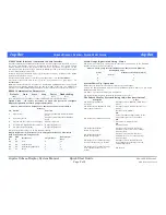
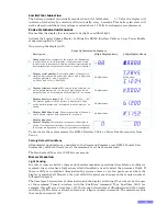
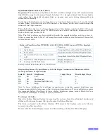
Links on Front Interface PCB 023-14-14-003 / 023-14-19-003 (nearest PCB to display).
Option
Function
A
Light Sensor
Swap Light Sensor Enabled / Disabled State
B
Zero switch
Swap Zero Switch Enabled / Disabled State
C
Scale switch (Counter or Torque modes
only)
Swap Scale Switch Enabled / Disabled State
D
Not fitted to 2 Digit Quadrature Counter.
See Separate Table (below).
Display Brightness 1.
E
Display Brightness 2


