40
M
AINTENANCE
O
PENING THE
S
UBSEA
D
ISPLAY
1.
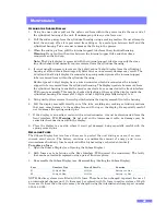
Using fine nose pliers pull out the nylon cord from within the groove inside the rear end of
the cylindrical housing of the unit. If undamaged put to one side for re-use.
2.
Pull the end cap away from the cylindrical housing using a rocking motion. Do not attempt to
twist the end cap off as it is prevented from doing so by a metal pin between itself and the
cylindrical housing. Take care not to damage the O-ring in the process.
3.
When the end cap is free, pull the internal support tube from the cylindrical housing.
Warning
: Do not pull on the wires between the internal support tube and the subsea
connectors on the end cap.
Note:
The 2 digit display is removed with the internal support tube leaving only the clear
lens which should not normally require removal from the cylindrical housing.
4.
It is not usually necessary to remove the 4 digit or dual 4 digit display from the cylindrical
housing at all and this is discouraged by Zetechtics, as unnecessary damage may result. The
4 digit and dual 4 digit display disconnects via sprung contact pins as the internal support
tube is removed from within the cylindrical housing.
Earlier types of 4 digit display have a wired connector, which disconnects as the internal
support tube is removed from the cylindrical housing. The display needs to be removed from
the cylindrical housing to enable the wired connector to be re-connected to the front interface
PCB upon re-assembly. This may be checked by looking at the rear of the display inside the
cylindrical housing. For removal of 4 digit or dual 4 digit displays follow steps 5 to 6.
5.
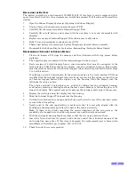
Using circlip pliers remove the circlip which retains the display assembly into the housing.
6.
Pull the display assembly directly out of the tube, avoiding any rocking or twisting motions
that may cause damage to the sealing face and O-ring on the display. Be especially careful
not to damage the sprung contact pins.
7.
If the display is an earlier version with a wired connector, it must be disconnected from the
front interface PCB.
Warning
: Do not pull on the interconnect cable, as damage may be
caused to the connections within the display.
8.
Place the display to one side, where it won’t get damaged, being especially careful with the
sprung contact pins.
R
EPLACING
F
USES
The Subsea Display has two fuses, these are to protect the unit wiring or users, if an over-
current event occurs. The battery contains a considerable amount of energy and in no
circumstance should any fuse be replaced with a higher rating or shorted out entirely.
To replace a fuse:
1.
Open the Subsea Display (see: Opening the Subsea Display).
2.
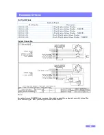
Both fuses are to be found on the Rear Interface PCB (nearest the connectors). The faulty
fuse can be extracted & replaced using a pair of fine nose pliers.
3.
Re-assemble the Subsea Display (see: Reassembling / Sealing the Subsea Display).
NOTE: Earlier systems were fitted with 1A fuses. These have been changed to permit the use of
an international charger unit. 1A fuses may be replaced with 3A fuses in earlier systems. If both
fuses are 3A fuses then the system may be charged using the international charger part number
023-14-02-005.
Fuse
Nanofuse Type
Farnell Part No.
Function
F1
3A Quick Blow
992-2180
Bve Line
F2
3A Quick Blow
992-2180
Battery –ve Line


