Blocking cancellation
Quick sinking
When you switch on the electric installation with the key of
the switching box (I), the lifting device remains blocked
electronically - the lifting and lowering function is
deactivated; on the EHR-B control panel the diagnostic
LED (7) and the vibration dampening LED (11) shortly
light up - the system self-test is in progress. The lifting
LED (8) and the lowering LED (9) are off. After a short
time permanent illumination of the diagnostic LED (7)
indicates the state of EHR-B blocking.
If the diagnostic LED (7) is permanently illuminated, the
control circuits are disconnected.
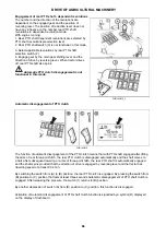
F_02_164
The engine can only be started if the engine (1)
is in position (b).
The EHR-B electro-hydraulic system is only active when
the engine is started.
Activation of the EHR-B system is only possible when the
lubrication indicator has gone off.
The blocking can only be cancelled (system activated)
with the engine running by moving the lifting lever (1) to
position (a) - short-time switching is sufficient.
By moving the lever (1) to position (c) you will bring the
three-point hitch to the position corresponding to the
element setting, i.e. the current position of controls (4), (5),
(6).
After the activation of the system EHR-B first
for safety reasons limits the lifting speed of the
hydraulic arms.
When the hydraulic arms first reach
the selected position, this safety limitation is
cancelled and then the lifting speed of the hydraulic
arms is normal.
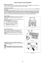
F_02_163
Lever (1) in position (d) - free position. You must hold the
lever in this position; after releasing the lever will return to
position (c) - the system works in accordance with the
setting of controls (3), (4), (5) and (6).
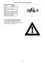
F_02_165
ELECTRO-HYDRAULIC SYSTEM
98
98
Summary of Contents for FORTERRA HD Series
Page 1: ...130 140 150 Tractor is Zetor Since 1946 OPERATOR S MANUAL FORTERRA HD 01 2014...
Page 3: ...2 2...
Page 11: ...NOTES 10 10...
Page 75: ...NOTES 74 74...
Page 79: ...NOTES 78 78...
Page 97: ...NOTES 96 96...
Page 115: ...NOTES 114 114...
Page 123: ...Placement of fuses in fuse box X18 ELECTRIC INSTALLATION 122 122...
Page 127: ...NOTES 126 126...
Page 153: ...NOTES 152 152...
Page 163: ...NOTES 162 162...


