background image

Front outlets of the outer hydraulic circuit

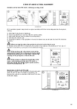
If the tractor is equipped with front outlets of the outer hydraulic circuit, the lever F-6-N-5 is 

used for their control.

If the tractor is equipped with a three-point hitch, the F-4-N-3 lever is used for its control. Quick 

couplers must not be connected at the time of three-point hitch usage connected because they are 

pressurized together like front three-point hitch!

After terminating the work with a front three-point hitch for further usage of the section with quick 
couplers 3 and 4 with the connection of three-point hitch, it is necessary to lift the arms of the front 

three-point hitch to transporting position and the lever of the cock of the front three-point hitch in the 

'closed' position.

Connecting machines and implements to the outer hydraulic circuit 

Auxiliary machines using oil filling of external hydraulic circuit must be filled with the same 

kind of oil, which is recommended for gear system of the tractor! Quick-couplers sockets of an 
auxiliary machine need to be properly cleaned before connecting.

Connecting machines and implements consisting of more parts 

During work with agricultural machines that consist of more parts (combinators, skids, harrows) and that 

have side frames hat are hinged to the central frame and during transport are folded to the vertical position 
by separate hydraulic cylinders controlled by the outer hydraulic circuit of the tractor, the folding of the side 

frames must always be controlled by the upward (backward) movement of the auxiliary distributor lever. The 

'lifting' branches of the cylinders must be connected to quick-couplers '1', '3' or '5'.

Connecting a rotational hydraulic motor 

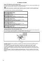
If a rotational hydraulic motor is connected to an outer outlet of the hydraulic system, its return branch must 

always be connected to quick-coupler '0'. 

Connecting a reversing hydraulic motor 

A reversing rotary hydraulic motor must be connected to quick-couplers '1' and '2' for functional reasons. 
However, relief valves must be inserted in both the branches in this case as they can reliably limit the 

pressure peaks during the stopping of the machine. The oil return lines from these valves are connected to 

quick-coupler '0'. 

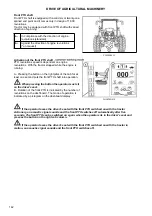
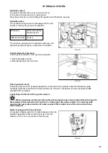
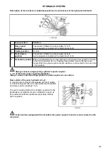
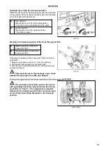
On request, the tractor can be equipped with external 
hydraulic circuit outlets located at the front. 

The quick couplers (5) and (6) are pressurized, the quick 

coupler (0) is directly connected to the transaxle area and 

are intended for return oil from external hydraulic devices.

FHSXS5N013

HYDRAULIC SYSTEM

148

Summary of Contents for FORTERRA HSX 120

Page 1: ...FORTERRA HSX 120 130 Tractor is Zetor Since 1946 140 OPERATOR S MANUAL 04 2020...

Page 2: ...erfect overview of how to use the tractor with maximum efficiency during various kinds of work If you observe the rules of tractor operation and maintenance and driving safety your new tractor will be...

Page 3: ...2...

Page 4: ...m 29 Windshield washer tank 30 Washer nozzle 30 Trailer brakes 30 Hydrostatic steering 30 Air cleaner 31 Cab filtration 31 Hitches 31 Inspection of fouling of coolers 32 After work with front implemen...

Page 5: ...unction of the heating and air condition system 54 Fast heating of the cabin area 55 Fast cooling of the space of the cabin 55 Immediately after cooling the cabin 56 Operation of heating or air condit...

Page 6: ...of the diesel particulate filter REGEN AUTO 90 Inhibition of regeneration of the diesel particulate filter REGEN INHIBIT 91 Driving operation 93 Starting the engine 93 Non permitted starting 93 If you...

Page 7: ...trailers 115 Connection of the ABS system of the trailer or semi trailer 115 The button for temporary deactivation of brakes of the trailer or semi trailer 116 Air brakes of trailers and articulated t...

Page 8: ...machines with greater inertia masses 144 Hydraulic system 145 Hydraulic system 145 Hydraulic pump 145 Control elements placement 145 Outer hydraulic circuit 145 Connecting and disconnecting quick coup...

Page 9: ...h solid discs 168 Ballast weights 169 Rear wheel weights 169 Bottom weights 169 Front weights 169 Weight of the front three point hitch 170 Valve for filling tyre tubes with liquid 170 Procedure of fi...

Page 10: ...drostatic steering 199 Replacing the hydrostatic steering hoses 199 Replacing coolant 200 Check and replacement of oil in gear box 201 Draining and checking holes 201 Checking the oil in gearbox 201 A...

Page 11: ...the rear tyres 216 Permitted combinations of wheels for tractors 216 Performance on rear PTO shaft 217 Lifting force of the three point hitch 217 Tensile force 217 Speed of tractor with engine revolu...

Page 12: ...mber 4 Tractor serial number When ordering spare parts and within all written and oral communication always specify the data of your tractor that should be written in the frames below Tractor type Tra...

Page 13: ...The right left front and back indications refer to the driving direction of the tractor FCL20S5002 LOCATION OF SERIAL NUMBERS 12...

Page 14: ...ticularly careful in these situations This symbol is used to indicate the parts of the instructions for use related to the environmental protection Or the parts describing handling of hazardous wastes...

Page 15: ...hift down Engine rotational speed instantaneous increase Anti lock brake system failure Engine rotational speed first preset Brakes failure Engine rotational speed second preset Parking brake Engine r...

Page 16: ...lower Distance covered by the tractor since the last reset of the value Suspended axle raise Total distance covered Suspended axle lock Fuel consumption per hour Read operator s manual Average fuel c...

Page 17: ...l first trailer Windscreen washer and wiper Turn signal second trailer Windscreen wiper Position lights Rear window wiper Hazard warning Exterior rear view mirror heating Master lighting switch Rear w...

Page 18: ...ler Rock damping Seat height adjustment cushion front Rockshaft raise Seat headrest height adjustment Rockshaft lower Bottom seat cushion Longitudinal adjustment controller PTO Power take off rotation...

Page 19: ...ggles etc Starting the engine The engine cannot be started by driving the tractor downhill The engine cannot be started by towing the tractor with another tractor Only start the engine from the driver...

Page 20: ...the tractor and trailer specified on the data plate of the tractor or on the rear wheel mud guard Do not use the differential lock when driving into a bend It is forbidden to get into and out of a mov...

Page 21: ...ified in the technical certificate of the tractor Persons that are not authorized to work with the attached implement must not stand between the tractor and the hitched machine implement Before puttin...

Page 22: ...r against rozjet m clutch is disengaged remove the key from the switchbox and lock the cabin With stopped engine only All work connected with refuelling cleaning lubricating and adjusting the tractor...

Page 23: ...work or before a meal you should wash yourself with a mild agent and treat your hands with a suitable ointment or cream When connecting and disconnection quick couplers of the hydraulic circuits use a...

Page 24: ...lation connection of other electric appliances are permissible due to its possible overloading The values of the electric installation are Nominal voltage 12 V Grounded minus pole pole Using starting...

Page 25: ...orbidden Using the seat for front passenger during the work with a tractor e g during the work on the fields is explicitly forbidden The use of safety belt on front passenger s seat is governed by val...

Page 26: ...e class I II III The category A includes all tractors with specified levels of vibration due to similar specifications of the construction The following table presents the results of the measurement o...

Page 27: ...PS conditions Tractors ZETOR supplied already from production with front end loader are equipped with cab roof according to point 2 From safety reasons series ZETOR tractors supplied without front end...

Page 28: ...observe special instructions related to accidents prevention and general rules related to technical safety la bour medicine labour hygiene and regulation defining operation on roads The manufacturer d...

Page 29: ...can be mounted to ZETOR tractors In case of additional assembly of further tractor equipment for working in the woods full responsibility is borne by the supplier and manufacturer of the protective s...

Page 30: ...e oil dip stick check the oil quantity in the engine and then check the connection of the engine lubrication system for leaks Maintain the oil level between the dipstick marks FCL20S5005 Check the con...

Page 31: ...ld be filled with distilled water or mixture for washers Antifreeze mixture for washers must be used in winter season for filling the washer tank C18N041 The washer nozzle is situated in the upper par...

Page 32: ...panel light is on See the chapter Maintenance instructions P18N102 Check and if necessary clean the cab ventilation air filters located in the left side roof lip The replacement of the filters depends...

Page 33: ...right side of the tractor Clean the front sides of the engine radiator gearbox radiators air conditioning condenser with compressed air blow air in the direction away from the engine Remove residual d...

Page 34: ...tting off the tractor Pay increased attention in the area of gear shifting lever and manual throttle lever Safety cabin is equipped with toned glass FCL20S5011 The door can be opened from the outside...

Page 35: ...between the mounted tools with maximum lifting of rear three point hitch and open rear window In case of collision we recommend to work with a closed window F18N076 The window is secured in the partl...

Page 36: ...in areas with reduced clearance C20N011 Pull out the sun visor of the windscreen 1 by pulling the handle in the direction of the arrow To return to the starting position briefly press the button 2 The...

Page 37: ...The interior lighting will automatically switch on for one to two minutes only in night mode when the battery disconnector is turned on or the ignition key is moved from position I to position 0 When...

Page 38: ...e has elapsed Aggregation opening If the cabin step illumination is on do not disconnect the battery by the battery disconnect Disconnect the battery only after the cabin steps illumination is off FHD...

Page 39: ...the lever to adjust the seat backrest inclination return the lever back to its original position to lock the backrest position 5 Foldable armrest 6 The armrest height locking adjustment release the c...

Page 40: ...wheel enables variable setting of position of the steering wheel both in terms of angle and height Height setting of steering wheel The setting is done by protrusion or retracting the steering wheel a...

Page 41: ...information see AGRICULTURAL MACHINES DRIVE 12 Rear PTO Speed Selection Button for more information see AGRICULTURAL MACHINES DRIVE F18N007 The windscreen wiper switch is located on the right pillar o...

Page 42: ...iper of the rear window is controlled by a single position switch 0 rear window wiper off 1 rear window wiper on F18N012 The front window washer control button is located on the right pillar of the ca...

Page 43: ...or work lights and beacons is located on the right side of the cab roof It is forbidden to use work lights during road traffic Use only original work lights When using non original work lights their p...

Page 44: ...ignition key is in position I in the key switch the panel is always on when the ignition key is moved to position 0 if no work light or beacons are on the panel turns off automatically after a certai...

Page 45: ...e activated automatically with a delay after the disconnector has been switched on only at dusk and at night night mode for a maximum time of 1 minute When the key is switched off the lights are activ...

Page 46: ...6 7 8 and 9 of the relevant light to switch on the relevant light for the reversing Press the ON OFF button 1 to turn on the work lights memory the backlight of the button changes to dark green functi...

Page 47: ...b Switching on the headlights on the cab is indicated by an illuminated symbol on the switch c Rear Fog Light Switch on Trailer or Semi trailer OFF ON Switching on the fog light is indicated by an ill...

Page 48: ...ghts on the cab are switched on If necessary the headlights can be switched between the brackets and the roof The high beam lights may only be switched on in the hood grill Direction lights lower beam...

Page 49: ...ia the key is disconnected The key can be removed C18N058 The voltage is connected to all the equipment excluding starter The key is in this position with the engine running C18N059 Starter and supply...

Page 50: ...lever enables to set engine revolutions in the whole range a to b FHSXS5N003 1 travel clutch pedal 2 foot brake pedals joint by a catch 3 throttle pedal C18N061 F front driving lever in the front N n...

Page 51: ...of gear shifting 2 buttons of shifting individual gears of multiplier C18N062 Reversing speeds can be shifted only by means of reversing lever The scheme is placed on the head of gear shifting lever...

Page 52: ...hines F18N085 Is placed in the upper part of right mudguard A detailed description of control and function of integrated hydraulic switchboard of external hydraulic circuit follows in Hydraulic equipm...

Page 53: ...y to recharge the battery at least once a month for self discharge Attention When the engine is switched off the control unit of the engine and of the exhaust system remains active for about 2 minutes...

Page 54: ...air circulation in the cabin PGPPN125 a heating valve closed b heating valve opened PGPPN126 0 ventilator off 1 slowly run of ventilator 2 medium run of ventilator 3 maximum run of ventilator PGPPN127...

Page 55: ...e cab area and blown back into the cab internal air circulation for quick temperature adjustment in the cab In this position the air intake from the outside of the cab is completely closed and an over...

Page 56: ...he internal air circulation by pressing the switch D and set the heating control A to the desired temperature Fast cooling of the space of the cabin PGPPN132 Proceed as follows 1 Turn the heating valv...

Page 57: ...e control B to position 1 or 2 Operation of heating or air condition with tractor s work When the internal air recirculation is switched on the fresh air supply is closed and the cabin space is exhale...

Page 58: ...C Changing the direction of air flow from the vent hold the vent by the slat and turn it in the direction of the arrows or tilt the slats in the direction of the arrows C20N031 To ensure a quick defr...

Page 59: ...tep on the fuel tank F18N087 Plug for draining dirt and fuel off the fuel tank is in its bottom F18N088 Add only urea Other media even a small amount e g diesel oil lead to the destruction of the syst...

Page 60: ...differential closure More information in chapter DRIVING 20 green signal lamp for connection of the front axle drive More information in chapter DRIVING 21 red signal lamp of a failure in the hydrosta...

Page 61: ...ument panel buttons P18N041 A reset button exit from menu of the instrument panel B enter button entry to menu of the instrument panel item selection confirmation in the instrument panel menu C button...

Page 62: ...stem 7 the information display part 8 name of the on screen menu 9 maintenance interval display disabled DPF regeneration display 10 torque multiplier selector switch signalization more in the chapter...

Page 63: ...3 total distance covered the value cannot be reset 4 distance covered by the tractor since the last reset of the value P18N043 1 urea consumption 2 degree of the DPF filter clogging by carbon black 3...

Page 64: ...ic switching off of the rear PTO shaft more information in the chapter Power of Agricultural Machines PHS18N020 There are data regarding automatic shifting of the torque multiplier on this screen more...

Page 65: ...mber value of air pressure in the air pressure system of the tractor When the air pressure is lower than 4 5 bar the background of the field is red when the air pressure is higher than 4 5 bar the bac...

Page 66: ...data by longer pressing of the button A RESET If you press the button A all data that can be reset on the selected screen would be reset Display manual brake If the tractor is not braked by a manual...

Page 67: ...ce monitor enables monitoring of the work area if the tractor is equipped with electro hydraulics Engine setup allows setting of DPF filter burning lock Language allows to set the language of the menu...

Page 68: ...e indicator of service inspection intervals FHSXS5N017 Press and hold the B button to enter the service menu Use the C and D buttons to select the settings item indicated by the arrow 1 Press the B bu...

Page 69: ...work and contact the service centre C Serious defects of the system The display cannot be switched to another screen The state is indicated by the signal lamp If this situation occurs stop the tractor...

Page 70: ...the tractor node from which you want the listing of defects to be displayed press the button B to enter the screen displaying the listing of defects for the selected tractor node 3 the listing of def...

Page 71: ...97 Press the button B to enter the service menu a use the buttons C and D to select the item Display settings press the button B to enter the screen with the display settings menu b the display settin...

Page 72: ...intensity of the display backlight The change of the backlight in percentage is indicated above the slider 3 100 percent is maximum backlight and 0 is minimum backlight Press the button B to confirm...

Page 73: ...ity of the lighting around the tractor when the day and night display backlights are automatically switched The change of the backlight in percentage is indicated above the slider 4 Press the button B...

Page 74: ...elect the setting item press the B button to go to the setting menu screen 1 Ground speed calibration 2 Resetting the interval of service inspections 2 Use the C and D buttons to select the desired fu...

Page 75: ...e saved at the last ground speed calibration by pressing B on the next screen d The screen asking to travel 100 m is displayed start the ground speed calibration by pressing the B button e The e scree...

Page 76: ...the processed area 3 end of the recording of the processed area 4 delete the recorded processed area for the selected user 5 delete the recorded processed area for all users The processed area displa...

Page 77: ...t values of the aggregation width can be changed for each user Enter the aggregation setting menu for the selected user Use the buttons C and D to select the aggregation that you can change and press...

Page 78: ...ready stored values If you need to change a user during the recording of the workspace close the record of the workspace select another user and the width of the aggregate start the recording of the p...

Page 79: ...rea level The signal lamp of low urea level is activated simultaneously with the fault signal lamp 4 or the stop signal lamp 3 on the instrument panel c Simultaneously the prompt to add urea to the ta...

Page 80: ...he cooling liquid is reduced and check the level of the cooling liquid if the cooling liquid starts to be overheated again when the engine is started stop the engine and contact the service centre If...

Page 81: ...apter B Warning Fault in the sensor circuit contact service Signalling of driver s seat PHS18N047 A signalling the operator left the driver s seat sit back on the driver s seat B defect there is a def...

Page 82: ...NOx in the exhaust gases The reducing agent injected into the exhaust system reacts in the SCR catalyst with the NOx emissions contained in the exhaust gases and reduces them to nitrogen N2 and water...

Page 83: ...e signal lamp of the diesel particulate filter by the subsequent acoustic signal and by the corresponding error code on the display of the instrument panel If this situation occurs increase the engine...

Page 84: ...nd the engine power can be reduced The catalytic reduction is stopped and the amount of harmful emissions in exhaust gases is increased When urea is added in the tank the catalytic reduction is restor...

Page 85: ...re vessels Urea freezes below the temperature of 11 C To ensure proper functioning of the SCR system urea with the concentration of 32 5 must be used Principles for safe handling of urea AUS 32 DEF Co...

Page 86: ...or is indicated and the system is switched into an emergency operation mode of the tractor with a reduced engine power P18N029 type of indication urea signal lamp defect signal lamp acoustic signal re...

Page 87: ...tank urea signal lamp display prompt to refill urea defect signal lamp acoustic signal reduction of power and limitation of engine revolutions signal lamp display type 1st degree of warning less than...

Page 88: ...st gases P18N032 Approaching first stage of reduction of engine power and speed is signaled to the tractor operator on the instrument panel display 1 or 2 together with an acoustic signal and warning...

Page 89: ...actor type First stage of power and speed reduction Counter value Second stage of power and speed reduction Counter value Agent quality counter 9 5 hours 25 minutes Agent quality counter 19 5 hours 25...

Page 90: ...filling of DPF filter with ash please contact authorized service Long term shutdown of tractor During a long term shutdown of the tractor the urea filling must be drained from the tank Before operati...

Page 91: ...iesel particulate filter REGEN AUTO The mode of automatic control of the treatment of exhaust gases The regeneration of the filter is started in case of need when a certain level of filling of the fil...

Page 92: ...filter regeneration by long pressing the button B Successful activation is indicated by the activated symbol on the display of the instrument panel In case that the regeneration must be started a mai...

Page 93: ...NOTES 92...

Page 94: ...t lights up 8 Wait until the glow plug light goes off the time depends on the coolant temperature If the glow warning light only blinks instead of the light there is a fault in the glow plug system Ch...

Page 95: ...lamp flashes once a second and the signal lamp 2 glows glowing in the emergency mode is performed similarly as at low temperatures regardless the temperature of the cooling liquid If the engine is at...

Page 96: ...Danger of injury due to electricity It is necessary to ensure tractor operator s instruction and regular revision of coolant heater including feeding cable pursuant to valid legislation of the state w...

Page 97: ...em red 2 The signal lamp of a less serious defect of the system orange 3 Operational protection signal lamp blue More information in chapter Instrument panel P18N048 If there is a serious error in con...

Page 98: ...ograms including their colours and the pictogram of the sounding acoustic warning signal In the right part of the label a required reaction of the tractor operator is described 1 If the signal lamp fl...

Page 99: ...e regeneration of the particulate filter is being performed Switching on the orange control indicator light 3 on the instrument panel while the engine is running indicates that there is a less serious...

Page 100: ...surface of the filter of solid particles is increased substantially There is an increased risk of fire or explosion during operation of the tractor in an environment with risk of fire or in an explosi...

Page 101: ...y driving forward Neutral driving backward FHSX18N021 The driver s seat is equipped with a safety switch which signalizes the system of driver abandoning the driver s seat If the tractor is started th...

Page 102: ...gears of multiplier 2 PHS18N005 H road speeds N neutral L reduced speeds Shifting of gears of the main gearbox with reduced speeds is the same as with road speeds Considering low speed of the tractor...

Page 103: ...rolling travel clutch with the function of automatic dead start for the regular operation of tractor with dead start gear shifting or the change of the driving direction 2 Clutch control button on the...

Page 104: ...coustic indication changes to uninterrupted indication Dead start of the tractor If at dead start engine revolutions are higher than 1400 rpm L gear of multiplier is automatically shifted not dependin...

Page 105: ...tractor starts 5 When you increase the engine revolutions simultaneously release the foot brake When depressing the clutch pedal the automatic dead start function is put off from operation Dead start...

Page 106: ...eed of more than 10 km h an acoustic signal starts uninterrupted tone the signal switches off after the shift of the lever back to N position when depressing the clutch pedal or pressing the button fo...

Page 107: ...control button on the head of gear shifting lever Press the clutch control button on the head of gear shifting lever At the same time release foot throttle pedal and shift the applicable gear speed Re...

Page 108: ...ns on the head of main gear shifting lever It is done without travel clutch pedal depressed under load H Increasing travel speed L Decreasing travel speed PHS18N033 Individual shifted gears of the mul...

Page 109: ...not depending on the shifted gear If the switch of multiplier preselection is activated the engine can be switched on and off and the stored values engine revolutions do not change Reading of values e...

Page 110: ...are reached the multiplier is automatically shifted without the driver s intervention In this case activated switch of multiplier preselection the manual shifting of the multiplier using the buttons...

Page 111: ...before the engine was switched off When both brake pedals are depressed the front axle drive will automatically connect Driving with engaged front axle drive Use front drive axle when rear wheels sli...

Page 112: ...ode can be done by pressing the manual mode button If the drive speed exceeds 20 kph the front axle drive is automatically disconnected Automatic drive disconnection is signaled by flashing a symbol o...

Page 113: ...rrectly You can turn off auto mode by pressing the button 1 again FHSX18N027 When the lower part of the button 2 is pressed the front drive axle suspension is locked the tractor front is lowered to th...

Page 114: ...ton To deactivate the differential lock press the button again or depress one of the brake pedals Switching from manual to automatic mode can be done by pressing the automatic mode button Differential...

Page 115: ...shifted in 0 position Brake the tractor with a manual brake F18N031 Shift from higher to lower gear in time when driving up the slope not to have a drop in engine revolutions under 1000 revolutions pe...

Page 116: ...ped with air or hydraulic brakes you must use the foot brake even from the beginning of the slope During braking with one brake pedal the brakes of the trailer are not operating FHD14N086 If the press...

Page 117: ...ed by the middle pin on the connector The button for temporary deactivation of brakes of the trailer or semi trailer can be used by the operator of the tractor with the connected trailer or semi trail...

Page 118: ...of 740 20 kPa If the pressure drops below 550 40 kPa secondary appliances are put out of operation by the by pass valve FCL20S5021 Warning signalization of air pressured drop Air pressure drop below 4...

Page 119: ...ximum allowed speed of the set of 30 km per hour Maximum allowed speed of the set is defined by maximum allowed speed of the slower vehicle of the set F18N035 Operating pressure is adjusted with the c...

Page 120: ...Brake valve of the trailer is done by the pressure of brake fluid from main braking rollers depending on the force effecting on the brake pedal The pressure on clutch head must be 12 15 MPa with maxi...

Page 121: ...is necessary to ensure its cooling 1 Before stopping the engine decrease the speed to 800 1 000 rpm and let it run without load for about 5 minutes 2 Move the manual throttle lever to the minimum fue...

Page 122: ...ilure Important warnings Hydrostatic steering pump failure is with oil pressure drop under 120 kPa behind a pump signalized on a dashboard by an applicable symbol Note When starting the tractor or wit...

Page 123: ...miting travel speed With the threat of exceeding the travel speed of 40 km h the maximum engine revolutions are automatically reduced This function cannot be switched off FHD14N068 DRIVING OPERATION 1...

Page 124: ...iciencies to be removed immediately you will thus prevent subsequent damage or endangered operation Keep the same procedure also after tractor complete overhaul In first 10 hours of operation From 100...

Page 125: ...NOTES 124...

Page 126: ...on the tractor equipment the front hitch is available in various versions For fixing the tow bar or tow rope to the front hitch always use the original pin which must be secured against extrusion wit...

Page 127: ...its height or disassemble it When you release the lever from position 2 the locking pins 3 will extend and the lever will automatically return to the initial position C18N098 When the lever 1 is move...

Page 128: ...ith a fixed pin module The swinging draw bar console module is located in the stage hitch console Swinging draw bar Disassembly 1 Release and remove the pins 1 2 Slide the swinging draw bar out in the...

Page 129: ...in the arrow direction you will retract the locking wedge 2 C18N104 The hitch for a single axle semi trailer may be equipped with a hook A or with a swinging draw bar B Replacing the hook with the sw...

Page 130: ...slower vehicle of the combination Hitch GTB30002Dmax trailer weight 5 900 kg Hitch GTP001 max trailer weight 20 000 kg Hitch X244 389SLD max trailer weight 11 500 kg Hitch type Allowed vertical stati...

Page 131: ...NOTES 130...

Page 132: ...sure that there are no unauthorized personnel near there is a risk of injury Display of revolutions of PTO shafts Replaceable end points of rear PTO shaft When the PTO shaft is switched on the PTO sh...

Page 133: ...release At 540 rpm the symbol on the rear PTO shaft shift button is not illuminated The selected number of revolutions of the rear PTO shaft is displayed on the dashboard display After restarting the...

Page 134: ...when the rear PTO shaft is stopped and the clutch pedal is depressed Standard and economical independent revolutions of rear PTO shaft FHSX18N006 The system used for the specific tractor is marked on...

Page 135: ...that when the PTO shaft is activated and the arms of the rear three point hinge are lifted the clutch of the rear PTO shaft is automatically deactivated and the shaft is stopped when the arms of the r...

Page 136: ...ON 2 the current position of arms of the rear three point hinge ON LIMIT 3 position of arms of the rear three point hinge where the clutch of PTO shaft is activated The values of individual items are...

Page 137: ...rear PTO shaft The rear PTO shaft is stopped if the arms of the rear three point hinge are in a position higher than the set value of OFF LIMIT the value 3 is higher than the value OFF LIMIT 2 When th...

Page 138: ...he rear PTO shaft will rotate even when the button 1 is released You must shortly press the button 1 again to stop rotation of the rear PTO shaft When handling the PTO shaft using buttons 1 the operat...

Page 139: ...least one second puts the rear PTO shaft into operation When pressing the button the operator must sit on the driver s seat D Rotation of the rear PTO shaft is indicated by the number of revolutions...

Page 140: ...seconds to bring the rear PTO shaft into operation When pressing the button the operator must not sit on the driver s seat H Rear PTO shaft rotation and selected rear PTO shaft mode are indicated by...

Page 141: ...ractor B This condition is indicated by the fact that the rear PTO speed is not displayed on the instrument panel display C Move the PTO speed preset lever to the middle neutral n position D This cond...

Page 142: ...eed selector E Depress the clutch pedal and shift the gears with the main shift lever and the travel direction with the reversing lever F Release the clutch pedal the rear PTO shaft starts rotating as...

Page 143: ...splined end point and it comes only in design of 1 000 revolutions Tractor may be equipped with front PTO shaft with varied direction of spinning a In compliance with the direction of engine revoluti...

Page 144: ...F Rotation of the front PTO is indicated by the number of revolutions on the dashboard The mode of Deactivation of the front PTO shaft If the operator sits in the driver s seat during work with the f...

Page 145: ...er minute 60 kW Rear 1000 per minute full output 540 per minute full output 1000E per minute 60 kW 540E per minute 60 kW F_02_46 Cardan shaft for drive of these machines must be equipped with the so c...

Page 146: ...al oil that remains in the socket or on the plug of the quick coupler For environmental reasons after every disconnection of quick couplers this residual oil must be removed with any textile material...

Page 147: ...the quick couplers The levers controlling both end sections are locked in the rear position at maximum oil flow rate into the quick couplers 1 or 5 After overcoming the increased resistance the locked...

Page 148: ...tral position Neutral 3 Front lower position Pressurized oil flows to quick couplers 2 4 6 Quick couplers connected to the return line 1 3 5 4 Front limit position With an increased force you can shif...

Page 149: ...ltural machines that consist of more parts combinators skids harrows and that have side frames hat are hinged to the central frame and during transport are folded to the vertical position by separate...

Page 150: ...speed 4 Setting the position of lifting device 5 Upper position restriction 6 Smooth setting of manual control automatic control 7 LED diagnostic 8 LED lifting 9 LED lowering 10 Engaging compensator...

Page 151: ...system is only possible when the lubrication indicator has gone off The blocking can only be cancelled system activated with the engine running by moving the lifting lever 1 to position a short time s...

Page 152: ...afety the steering axle is not unloaded so much 2 Stabilization of the transported implement 3 Reduced dynamic stress of the hydraulic system and the rear three point hitch During the adjustment of th...

Page 153: ...mbol of the maximum lowering speed Symbol of the minimum lowering speed C18N117 For permanent work with free hydraulic system e g during work with a plough with a support wheel the position of the con...

Page 154: ...18N120 Do the step according to Cancel blocking part Set the control 6 to hitchtronic AHC position By control 4 set the working depth of tools attached to rear three point hitch When the implement att...

Page 155: ...g of the control system and the Blocking cancellation must be repeated C18N121 1 Lifting 2 Lowering The movement only lasts as long as the buttons are held External hydraulic control buttons are funct...

Page 156: ...lic system C18N123 Have EHR B errors repaired by a specialized workshop Flashing combination of the diagnostic LED 7 Error category Error description Long pause No of flashes Short pause No of flashes...

Page 157: ...in 3x 2x Left dynamometric pin A Faulty contact or interrupted conductor of the dynamometric pin Short circuit of the dynamometric pin conductor Possible overloading of the dynamometric pin 3x 4x Lowe...

Page 158: ...70 mm of openings of connecting balls of the lower draw bars according to ISO 28 mm of the upper draw bar opening 25 mm Category III N Hitch axis length 870 mm of openings of connecting balls of the l...

Page 159: ...raw bars Fixed and free position of the lower hydraulic draw bars Lifting draw bar see fig A After disconnecting the upper end of the lifting draw bar from the pin of the hydraulic arm make the adjust...

Page 160: ...2 are slid onto draw bars and automatically are locked in working position by means of locking pegs 1 Always check the position of slipped out end pieces and locking pegs see fig 3 E459 Both the lower...

Page 161: ...of the tractor above the front axle The use of this hydraulic lock is recommended even if no equipment is connected to the three point hitch C18N128 The hitch is equipped with two hydraulic cylinders...

Page 162: ...bars of the front three point hitch 1 Release and remove the pin 1 from the opening 2 Lift the arm from position A to position B 3 Lock the arm by inserting the pin 2 in the opening 2 and secure the...

Page 163: ...NOTES 162...

Page 164: ...screws back with pads and lock with nuts Tighten nuts with a torque of 270 300 Nm The nut of front wheels to be tightened with a torque of 250 290 Nm After every release of a foot joint tighten the s...

Page 165: ...heels and mount with rim offset to the inside Nuts tightening front wheels to be tightened at a torque of 250 290 Nm After travelling the distance of 100 m with an unloaded tractor tighten the nuts ti...

Page 166: ...nt driving axle PGPPN096 Note Tractors are in standard equipped with hydrostatic device Set the wheel symmetrically with longitudinal axis of a tractor Measure the distance between rims in the front o...

Page 167: ...f tires used C18N037 Set the stops always with any wheel track change or tire replacement with front drive axle Wheel stops with front drive axle must be set so that there would be a distance of at le...

Page 168: ...a torque of 270 300 Nm and nuts of screws connecting a disc with wheel shaft with a torque of 400 470 Nm Tighten the screws to a prescribed value after every release of foot joint After travelling a...

Page 169: ...The gauges of the tractor rear wheels equipped with solid discs Rear wheels track mm mm 18 4 38 1725 460 85R38 1725 480 70R38 1725 520 70R38 1725 600 65R38 1725 WHEEL TRACK CHANG 168...

Page 170: ...hat are accessible after removal of the battery holder Combination of weights pcs Mass of weights kg 2 2x34 68 FHD20S5N047 The front weights of the can type are suspended in the tool carrier They are...

Page 171: ...iron 460 Concrete 800 FHSXS5N011 All the tubes of the rear wheels are equipped with a valve that makes it possible to fill the tubes with liquid with the use of an adapter Filling the tubes of the fr...

Page 172: ...way Water must not freeze in a tyre Procedure of draining liquid from the tyres PGPPN182 1 Unload the tyre by lifting the tractor and turn it with the valve upwards A 2 Deflate the tyre and unscrew th...

Page 173: ...refully with it Remove spilt drops with clean water 3 Before filling leave the solution to cool down Observe the prescribed quantity of hydrated lime 4 The solution must not get in contact with metal...

Page 174: ...ractor frame using the battery disconnector This eliminates accidental short circuits at the terminals During any manipulation or repair of the starter the negative terminal of the battery must be dis...

Page 175: ...ssary to recharge the battery at least once a month for self discharge Attention When the engine is switched off the control unit of the engine and of the exhaust system remains active for about 2 min...

Page 176: ...e handle it with proper care If your skin or clothes get stained by electrolyte wash the skin or clothes with water and neutralize them with soap 4 During charging hydrogen is released from the electr...

Page 177: ...electric connection of the alternator terminals and proper grounding of the alternator Poles of the alternator may not be re versed even for a short time Electric installation overload Charging is ind...

Page 178: ...the tractor cabin The fuse panel C is accessible after disassembly of the right side cover of the control bracket and it is accessible from the tractor cabin During replacement of fuses it is necessa...

Page 179: ...Fuse panel B Tractors without light controller only FHSXS5N010 ELECTRIC INSTALLATION 178...

Page 180: ...F14 7 5A Air conditioning F15 15A Mirrors heating F16 15A Rear window heating F17 15A Driver s seat compressor F18 25A Three pole DIN9680 socket F19 15A Work lights under the roof F20 15A Work lights...

Page 181: ...Fuse panel B Tractors with light controller only FHSXS5N008 ELECTRIC INSTALLATION 180...

Page 182: ...r two pole socket F14 7 5A Air conditioning F15 15A Mirrors heating F16 15A Rear window heating F17 15A Driver s seat compressor F18 25A Three pole DIN9680 socket F19 Not used F20 Not used F21 15A 8 T...

Page 183: ...ket in the cab F41 25A Three pole socket on the right fender F43 10A Driver s seat heating F46 7 5A Socket in the cab F47 10A Trailer braking system F48 10A Trailer braking system F49 5A Trailer braki...

Page 184: ...of symmetry of the tractor Check the adjustment of the headlights at the shipping weight of the tractor The front roof headlights may only be used when driving on public roads when the tractor carrie...

Page 185: ...on Voltage Power Bulb type 1 Low beam headlight 12V 60W HB3 2 High beam headlight 12V 60W HB3 3 Work light plowing 12V 65W H9 4 Low headlight alternative 12V 55W H7 5 Direction indicator light 12V 21W...

Page 186: ...p Checking the function of charging signal lamp Checking the function of driving signal lamp Checking the function and tightness of the control circuit Checking the function and efficiency of the trac...

Page 187: ...tractor or tractor after a general overhaul hour counter reading 100 500 1000 1500 2000 2500 3000 subsequently after every hours Check and adjust valve play o o 2000 Check the opening pressure of inj...

Page 188: ...or once every 2 years Replace coolant once every 2 years Replace oil in the gearbox and final drive housing o o 1000 Clean the magnet and strainer element of the suction filter of the hydraulic pump...

Page 189: ...ments stated in this service manual ZETOR service fillings To maintain best operational characteristics of your tractor original operational Zetor fillings are recommended to be used Motor oils Engine...

Page 190: ...30 GL 4 Viscosity grade SAE Performance level category API 80W 80W 90 GL 4 GL 5 LS Typ Classification MOGUL LA 2 ISO 6743 9 CCEB 2 3 ISO L XBCEA 2 FRIDEX STABIL FRIDIOL 91 or FRICOFIN S and deminerali...

Page 191: ...rth America as Diesel Exhaust Fluid DEF The lifetime of urea without the loss of the quality is influenced by storage conditions It crystallizes at 11 C and over 35 C it initiates hydrolytic reaction...

Page 192: ...protective equipment occupational footwear protective gloves safety goggles etc Prior to starting the work secure the tractor against movement using manual brake Lubrication must be performed only wh...

Page 193: ...semi trailer Front three point hitch Position number Name Number of greasing points 1 Greasing points 25 Pos no Identification No of lubrication points 1 Hook pin bearings 0 to 4 by version PCLUN033...

Page 194: ...rhaul in accordance with the instructions for running in a new tractor Perform the maintenance in the same way as with a new tractor Pos no Identification No of lubrication points 1 Pins of auxiliary...

Page 195: ...NOTES 194...

Page 196: ...nd hydraulic system Opening the hood To open the hood Unlock the hood by pushing using a suitable tool e g a screwdriver on the rod 1 in the direction of the arrow The rod is located in the hole on th...

Page 197: ...er 2 Coat the rubber sealing with oil that you will fill the engine with and tighten the cleaner by hand When the sealing gets in contact with the block sealing tighten the cleaner again by 3 4 to 1 1...

Page 198: ...fore bleeding place a suitable container under the engine to collect dripping fuel from the filter and injection pump FHD20S5N055 1 Prime the fuel system with several strokes of the manual control of...

Page 199: ...1 PGPPN148 Draw the main dry cleaner cartridge 2 Wipe the plastic cover of the filter using a suitable cloth If the main cartridge is not damaged no dust on the inside of the cartridge perform the reg...

Page 200: ...sides 5 At maximum engine speed turn the steering wheel 3x alternately slowly and quickly to both sides up to the wheel limit stops 6 Stop the engine and lower the tractor on the front wheels FHD20S5...

Page 201: ...e drain tap and the plug leave the heating tap open 5 Fill the cooling system with coolant up to the filler neck in the expansion tank and close with the overpressure plug C FH12N084 6 Start the engin...

Page 202: ...et is checked by oil level indicator which is placed at the right rear part of the gearbox behind the right hydraulic roller Carry out the check always with the engine stopped A Standard oil filling F...

Page 203: ...place the filtration element 3 Reassemble the body of the cleaner FHD20S5N059 Oil cleaner is placed on the left side of the gearbox The cleaner clogging is signalized by a control on dashboard lightin...

Page 204: ...nscrewing control screw the level of oil must reach the brim of checking hole 2 filling oil hole at the top 3 draining hole hole at the bottom FCL20S5046 The inspection and filling plug of oil 1 is si...

Page 205: ...ts mounting 2 Remove the protective package from the new filter 3 Insert the filter into the air duct orifice in such a way to make the air flow direction correspond to the flow direction through the...

Page 206: ...ith compressed air or flush with pressurized water against the driving direction of the tractor Then insert the radiator back and fasten properly Make sure that the hoses to the oil radiator are route...

Page 207: ...e non return valve If there is the maximum pressure in the air reservoir A the tyres cannot be inflated In this case you must first reduce the pressure with the condensate drain valve located in the b...

Page 208: ...o increase the load bearing capacity of the tyres except the above mentioned cases by further in creasing the inflation pressure above the values mentioned in the table while si multaneous decreasing...

Page 209: ...iod inflate the tyres to the value required for road transport In case of a longer period of inactivity of the tractor storage support the tractor and reduce the pressure in the tyres to the minimum t...

Page 210: ...A does not need to be adjusted The belt is tensioned automatically Tensioning the V belt of the AC compressor If the V belt B is properly tensioned its deflection must be 5 5 mm when the belt is subje...

Page 211: ...Perform the adjustment in such a way that the self locking nut 1 of the parking brake draw bar can touch the pin 2 in the disc brake lever 3 After this basic adjustment check the operation of the par...

Page 212: ...ballast weights Outline length with hitches without the front three point hitch 4520 without ballast weights Width over the rear fenders 2270 Height to the exhaust outlet 2943 Tractor height to the u...

Page 213: ...100 2 Fuel consumption at the nominal engine speed 2200 rpm ECE R120 g kWh 229 221 229 9 Max torque 1 480 rpm ECE R120 Nm 507 3 557 6 606 6 Inclination Mt ECE R120 35 5 38 39 Fuel consumption at the m...

Page 214: ...euvrability condition Travelling speed km h Wheel track mm 1590 1655 1730 1740 1800 1880 1890 1955 2030 2040 8 5500 5500 5500 5500 5400 20 4400 4400 4400 4400 4100 30 4400 4400 4400 4400 4100 40 4400...

Page 215: ...d inflation values are minimum valued adapted to the current tyre load so that the tyre deformation can remain in the range in which all the operation requirements are met During operation on a hard b...

Page 216: ...re is a dimensional equivalent of the 18 4R38 tyre The specified inflation values are minimum valued adapted to the current tyre load so that the tyre deformation can remain in the range in which all...

Page 217: ...n of tyre Equivalent 1 MITAS 340 85R24 440 65R24 280 85R28 13 6R24 11 2R28 420 85R38 480 70R38 16 9R38 2 MITAS 440 65R24 280 85R28 11 2R28 460 85R38 520 70R38 600 65R38 270 95R48 18 4R38 11 2R48 3 MIT...

Page 218: ...stage from 100 hours on 71 0 78 6 84 2 Lifting force through the range Max lifting force On the hitch ball On ISO frame On the hitch ball On ISO frame 36 kN 32 2 kN 46 8 kN 33 9 kN Lifting force thro...

Page 219: ...8 32 8 29 6 30 5 L 27 5 28 3 25 6 26 4 3 H 24 2 25 0 22 5 23 2 M 20 9 21 6 19 5 20 1 L 18 1 18 7 16 8 17 4 2 H 15 9 16 4 14 8 15 2 M 13 7 14 1 12 7 13 1 L 11 86 12 23 11 0 11 4 1 H 10 77 11 11 10 0 1...

Page 220: ...M 403 731 466 846 L 347 631 402 730 2 H 304 552 351 638 M 264 480 305 555 L 228 416 265 480 1 H 206 376 239 434 M 179 325 207 376 L 155 282 179 325 Reduces speeds 5 H 922 1 675 1 066 1 937 M 796 1 44...

Page 221: ...e tractor Turning direction PTO speed engine speed PTO speed engine speed right a 1000 1920 1146 2200 left b 1000 2000 1100 2200 Track width front 1855 mm Tyre dimensions front 420 70R24 rear 1725 mm...

Page 222: ...d GH kg total machine weight suspended in the rear rear load GV kg total machine weight suspended in the front front load a m distance between the gravity centre of the front carried machine front loa...

Page 223: ...se of the tractor designed for the front axle should be recorded in the table 4 Calculation of the real total load G tat If the necessary rear axle load cannot be reached with the rear attached machin...

Page 224: ...ide moving machines side ditch trimmers and similar types of aggregation there is an unequal distribution of the load on the right and on the left side of the tractor axle It is necessary to ensure th...

Page 225: ...NOTES 224...

Page 226: ...tion of drive 105 Change the direction of drive using the clutch pedal 105 Change the direction of drive by means of reversing lever 105 Check and replacement of oil in gear box 201 Check of the Adjus...

Page 227: ...n tractors equipped with non removable discs 164 Front windshield defrosting 57 Front wiper speed switch 40 Fuel for Zetor engines which are equipped with diesel paricle filter 190 Fuel system leaks 2...

Page 228: ...ols 24 PTO revolutions preselection lever 51 Q Quick sinking 150 Quick couplings with drip collection 145 R Rear outlets of the outer hydraulic circuit 147 Rear PTO shaft revolutions preselection leve...

Page 229: ...g of the width of aggregation 76 The socket for connection of the electrical installation of the trailer or semi trailer 119 The way of controlling the travel clutch by 102 Three gear torque multiplie...

Page 230: ...229...
Page 231: ...rator s manual FORTERRA HSX 120 FORTERRA HSX 130 FORTERRA HSX 140 Edition 4 100 2020 Publication No 222 213 550 6 2020 ZETOR TRACTORS a s Department of Technical Documentation Trnkova 111 628 00 Brno...

Page 232: ...www zetor com zetor zetor com Made in EU...

Reviews: