background image


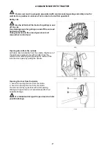
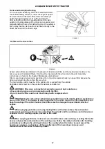
Lights switch 

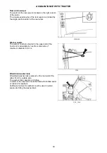
Switch of warning lights 

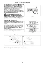
Lights switch between the grill and the cabin 

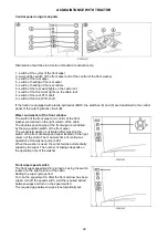
Direction lights, lower beam head lights, head lights and horn switches 

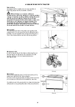
a - illumination off 
b - side and end point lights on, illumination of licence 
label, illuminated 
c - all devices on in 'b' position. Lower beam head lights or 
head beam lights are engaged (according to the position 
of direction lights, lights and horn switches). 

F56


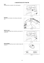
a - warning lights on 
b - warning lights off 
Function of warning lights is signalized by interrupted 
blinking control on the dashboard. 

F58


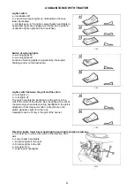
a - roof lights on 
b - roof lights off 
The switch controls the illumination in the grill or in the 
roof of the cabin of the tractor. Use the lights in the roof of 
the cabin only when tools covering headlights in the grill is 
attached in front three-point hitch. A lit symbol on the 
switch signalizes light on in the roof. 
Headlights can be lit only in the grill of the bonnet. 

F59


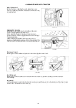
a - Acoustic horn - press the switch in the direction of an 
axis 
b - Lower beam head lights 
c - Direction lights to the right 
d - Direction lights to the left 
e - Acoustic horn 
f - Lower beam headlights 

X139


ACQUAINTANCE WITH TRACTOR

41

Summary of Contents for PROXIMA HS Series

Page 1: ...Tractor is Zetor Since 1946 OPERATOR S MANUAL PROXIMA HS 06 2017 100 110 120 0 06 6 201 2017 7 100 110 120...

Page 2: ...and get a perfect overview of how to use the tractor with maximum efficiency during various kinds of work If you observe the rules of tractor operation and maintenance and driving safety your new trac...

Page 3: ...2...

Page 4: ...teering 24 Air cleaner 24 Cab filtration 25 Hitches 25 Inspection of fouling of coolers 25 After work with front implements and in case of cooler clogging 25 Tyres and wheels 26 Short functional test...

Page 5: ...put shaft 45 Lever of hand brake and hitch for single axle trailer 45 Battery disconnector 46 Fuel tank 46 Fuel tank drain plug 46 Urea tank 47 Instrument panel 49 Instrument panel signal lamps 49 Ins...

Page 6: ...ating 82 Error signalling 82 Indication of the limitation of the engine power and engine revolutions 82 Diesel particle filter 83 Filter of solid particles indication of operation and failures of the...

Page 7: ...g of a single axle trailer 103 Uncoupling of a single axle trailer 104 Hook of the mounting for a single axle trailer 104 Coupling with a trailer or semi trailer 104 Maximum permissible vertical stati...

Page 8: ...working with the three point hitch 137 Height adjustment of the lifting draw bars 138 Fixed and free position of the lower hydraulic draw bars 138 Limiting draw bars 138 Upper pull rod 139 Selection o...

Page 9: ...n the rear axle gantries 164 Oil for the front driving axle 164 Oil for the hydrostatic steering of the tractors 164 Specification of oils for Zetor engines equipped by diesel particle filter 164 Spec...

Page 10: ...active carbon 181 Carbon filter installation instructions 181 Air conditioning maintenance 182 Draining condensate from the air reservoir 182 Checking the air systems for leaks 182 Working pressure of...

Page 11: ...tor 40 km h 198 Backward travelling speed of the tractor 40 km h 199 Rear independent PTO shaft rotation 199 Speed of the Zuidberg front PTO 200 Clearance circle and turning circle diameter 200 Calcul...

Page 12: ...4 Tractor serial number When ordering spare parts and within all written and oral communication always specify the data of your tractor that should be written in the frames below Tractor type Tractor...

Page 13: ...The right left front and back indications refer to the driving direction of the tractor G3 LOCATION OF SERIAL NUMBERS 12...

Page 14: ...symbol refers to optional tractor accessories installed by the manufacturer on the customer s request Instruction manual s passages related only to models equipped with DPF diesel particle filter are...

Page 15: ...hen driving on a slope and muddy sandy icy or uneven ground z Observe the maximum specified inclination angle i e 12 z Respect the total permissible weight of the tractor and trailer specified on the...

Page 16: ...ght hand side door pay attention being in space of shifting lever and hand throttle control z Brake the tractor with parking brake before leaving tractor with running engine z Before leaving the tract...

Page 17: ...the end of their service life you must observe relevant provisions of valid acts and implementation directives of these acts of the country where the tractor is used The last seller of the tractor is...

Page 18: ...n the tractor thoroughly from chemically aggressive substances and neutralize them after the termination of the work according to the manufacturer s instructions Driver s seat If the driver s seat is...

Page 19: ...ts of measurement on testing bench are listed in the following table pursuant to directive 78 764 EEC The value a wS is an adjusted value of effective acceleration balanced according to vibration move...

Page 20: ...re equipped with cab roof according to point 2 From safety reasons series ZETOR tractors supplied without front end loader with standard roof pursuant to point 1 must not be equipped or used with fron...

Page 21: ...bserve special instructions related to accidents prevention and general rules related to technical safety la bour medicine labour hygiene and regulation defining operation on roads z The manufacturer...

Page 22: ...an be mounted to ZETOR tractors In case of additional assembly of further tractor equipment for working in the woods full responsibility is borne by the supplier and manufacturer of the protective str...

Page 23: ...NOTES 22...

Page 24: ...he oil dip stick check the oil quantity in the engine and then check the connection of the engine lubrication system for leaks Maintain the oil level between the dipstick marks E6g Check the connectio...

Page 25: ...fectiveness of brakes of the tractor with a trailer Trailer hydraulic brakes Check tightness of hydraulic brakes of the trailer and effectiveness of brakes of the tractor with a trailer G9 z Check the...

Page 26: ...out or blowing with compressed air Do the cleaning or replacement of the filter elements after removing the covering grills in the roof overhang At the customer s request we supply filters with active...

Page 27: ...value Check and if necessary retighten the bolts of the front and rear wheels Never drive with loose wheel bolts G11 After starting the engine check whether the hydrostatic steering failure engine lu...

Page 28: ...care in the area of gears lever and manual fuel control lever G101 Left cabin door is lockable from the outside Right door of the cabin are equipped only with a button from the outside After unlockin...

Page 29: ...25 The window is secured in the partly open position with a plastic latch You can open the door by lifting the latch towards yourself upwards and pushing it into the groove Then the window will be sec...

Page 30: ...e right mudguard FH12N025 The tools box is located on the right side of the driver s seat P15n019 On the right rear panel there are the three pin socket 12V and the firer P15n020 To be turned on and o...

Page 31: ...seat in the direction of an arrow 4 Before the drive or starting the work adjust rear view mirrors so that they enable to monitor the whole drive way or working field F_02_12 Aggregation opening serve...

Page 32: ...of rear seat cover Spring stroke is 120 mm Do not adjust the seat when driving Danger of accident C131 The seat can be longitudinally adjusted within range 75 mm 11 positions after unlocking of left h...

Page 33: ...controller to the lower position to lock it 8 The seat height adjustment and seat suspension adjustment according to the weight of the driver push the controller to increase the air pressure in the p...

Page 34: ...pressing the lever 1 in the opposite direction than shown by the arrow W1 Tilting column of steering wheel enables variable setting of position of the steering wheel both in terms of angle and height...

Page 35: ...bin F13BN009 a heating valve closed b heating valve opened F_02_16_a 0 ventilator off 1 slowly run of ventilator 2 medium run of ventilator 3 maximum run of ventilator F_02_16_b Do engagement and dise...

Page 36: ...F11N009 Proceed accordingly 1 Turn the heating valve control A to the position on the right fully opened heating valve 2 Set air circulation in cabin control D to the position of inner circulation 3 S...

Page 37: ...en spraying pesticides and using the heating filter with active carbon the recirculation controller should be in position air is drawn into from the outside and the fan controller should be in the pos...

Page 38: ...checked Used filters must be damaged in specialized collection centres When spraying pesticides and using heating filters with active carbon the recirculation control must be in the position of air s...

Page 39: ...the front wiper and control of the front washer are located on the right column of the cabin The double speed engine of the front wiper is controlled by the two position switch of the front wiper The...

Page 40: ...le is situated in the upper part of the hood and is adjustable by needle or steel wire of maximum diameter 0 8 mm C128 Windshield washer tank is placed on the rear wall of the cabin from the outside s...

Page 41: ...g lamp function is signalized by a lit symbol on a switch e Warning lights switch f Front drive axle button Engaged front drive axle is signalized by lit symbol on a switch g Beacon switch off on h Wo...

Page 42: ...lights is signalized by interrupted blinking control on the dashboard F58 a roof lights on b roof lights off The switch controls the illumination in the grill or in the roof of the cabin of the tracto...

Page 43: ...us position after loosing Illuminating of the symbol on the switch indicates that the differential lock is engaged The differential lock is automatically disengaged after pressing the brake pedals At...

Page 44: ...onnected to all the equipment excluding starter The key is in this position with the engine running S44 Starter and supply of all equipment is connected in this position apart from wipers washer cab v...

Page 45: ...front driving lever in the front N neutral R back driving lever at the back X212a main gear shifting lever 1 button for disengaging clutch on the head of gear shifting 2 buttons of shifting individual...

Page 46: ...p or pushing down the lever The tractor can be equipped optionally by 6 8 or 21 groove termination of the output shaft Shifting of 540 and 1 000 or 540E min 1 is possible regardless to the number of g...

Page 47: ...During long time shutdown repairs failure or crash immediately disconnect the battery by means of the battery switch Battery switch is located on the left hand tractor side in front of the cab A batte...

Page 48: ...Urea tank The tank for urea is located in the right side of the tractor and is equipped with the blue plug of the filling hole The tank volume is 30 litres PW15N019 ACQUAINTANCE WITH TRACTOR 47...

Page 49: ...NOTES 48...

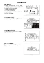
Page 50: ...signal lamp yellow Lights up with air filter clogging 11 Urea level signal lamp red orange 12 SCR signal lamp red 13 SCR signal lamp orange 14 Indicator red of a failure in the hydrostatic control sy...

Page 51: ...achieved 3 Indicator of engine revolutions at which nominal revolutions of the rear PTO at standard revolutions of the rear PTO shaft are achieved E display Instrument panel buttons A Rolling up in t...

Page 52: ...itch 4 engagement of differential locks 5 maintenance interval exceeded 6 shifting lever position reversing F driving forward N neutral R reversing 7 main field of display 8 secondary field of display...

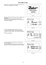
Page 53: ...rrent time in 24 hour format is displayed PW15N003 There are data regarding PTO shafts in this screen 1 Front PTO shaft revolutions if the shaft is activated 2 Rear PTO shaft revolutions when the shaf...

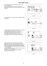
Page 54: ...engine start In the secondary field 2 the immediate consumption of the fuel is displayed The entry is automatically cleared when the engine is switched off PW15N008 In the main field 1 the amount of...

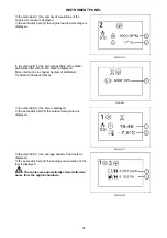
Page 55: ...s displayed More information in chapter System of Additional Treatment of Exhaust Gases P15N065 In the main field 1 the time is displayed In the secondary field 2 the outdoor temperature is displayed...

Page 56: ...set zero the value at the beginning of the measurement The value is updated every 10 s Manual zeroing reset of data Except automatic zeroing of data these entries can be zeroed manually For manual zer...

Page 57: ...s of the tractor 1 remaining to the maintenance date is displayed on the display Exceeding the service interval If the tractor is not braked by a manual brake a warning is displayed on a display lette...

Page 58: ...by switching the corresponding signal lamp acoustic signal and error message in the instrument panel display If the error is indicated the signal lamp still glows even though the display is switched...

Page 59: ...lay of the defect is minimized into the main field All the tractor s functions remain active it can happen that some of the functions is not undepreciated The state is indicated by the signal lamp If...

Page 60: ...will enter the service menu by a longer pressing of A button The selection of items to be done by B and C buttons The selected item is marked by an arrow 1 Exit from service menu By buttons B and C s...

Page 61: ...oll between individuals defects 1 sequence number 2 defect code 3 code of defect specification 4 number of defect repetitions Return to the main screen by pressing button C ENTER Display setting langu...

Page 62: ...ctor to the beginning of the 100 metre track enter the service menu by pressing A button select the item 1 by B and C buttons and by pressing A button go to calibration menu select the item 2 by B and...

Page 63: ...ION menu b Use the buttons B and C to select the item SETTING OF PTO SPEED indicated with the arrow b and by pressing the button A ENTER you enter the next screen c Screen for setting the rear PTO sha...

Page 64: ...successive pressing of button A ENTER we change the value of hours in the display changes are displayed directly in the position 5 Use buttons B and C to select the item minutes 2 by successive press...

Page 65: ...ion of regeneration of the DPF filter for safety reasons only Enter the menu of the engine setting by long pressing the button A on the instrument panel The service menu screen b is displayed To enter...

Page 66: ...llowing signal lamps operational protection 2 defect 3 or stop 4 and the prompt to refill urea in the tank appears in the display of the instrument panel c together with an acoustic signal Always refi...

Page 67: ...d stop the engine and contact the service centre If high temperature of cooling liquid is indicated warning the reaction of the system is reduced engine power by 25 High oil temperature in the gearbox...

Page 68: ...immediate replacement of the oil filter cartridge of the gearbox distributor see chapter Maintenance Guidelines Full pushing filter of the hydraulics C15N122 The full oil filter of the hydraulics is...

Page 69: ...NOTES 68...

Page 70: ...ount of NOx in the exhaust gases At the same time the reduction agent injected into the exhaust system reacts in SCR catalyst with NOx emissions contained in exhaust gases which are reduced to nitroge...

Page 71: ...the orange signal lamp of the diesel particulate filter by the subsequent acoustic signal and by the corresponding error code on the display of the instrument panel If this situation occurs increase...

Page 72: ...the engine power can be reduced The catalytic reduction is stopped and the amount of harmful emissions in exhaust gases is increased When urea is added in the tank the catalytic reduction is restored...

Page 73: ...re vessels Urea freezes below the temperature of 11 C To ensure proper functioning of the SCR system urea with the concentration of 32 5 must be used Principles for safe handling of urea AUS 32 DEF Co...

Page 74: ...ument panel and by the subsequent acoustic signal If the error is not eliminated it is indicated every time when the engine is started The reason for the indication may be in not meeting the required...

Page 75: ...the instrument panel 2 x 3 s 1st degree of limitation less than 5 orange signal lamp flashes 1 Hz Continuous display The prompt disappears after pressing any button on the instrument panel 2 x 3 s re...

Page 76: ...68 EC or 1 5 h for Tier 4f EPA expires limitation of the engine power with continuous starting is activated Note A warning message on the display 1 or 2 is displayed according to the type of the trac...

Page 77: ...filling of DPF filter with ash please contact authorized service Long term shutdown of tractor During a long term shutdown of the tractor the urea filling must be drained from the tank Before operati...

Page 78: ...l of the treatment of exhaust gases The regeneration of the filter is started in case of need when a certain level of filling of the filter with carbon black temperature of exhaust gases and engine lo...

Page 79: ...of the filter regeneration b by long pressing the button A Successful activation is indicated by the activated symbol c in the upper right corner of the instrument panel display In case that the rege...

Page 80: ...ion 4 that the PTO switches are off If the clutch pedal is not pressed the engine cannot be started the starting interlock switch is not actuated Note Before the entire starting we recommend you to pr...

Page 81: ...pursuant to valid legislation of the state where the tractor is operated at least prior to each winter period Starting the engine PW15N030 1 Put the key in ignition 0 position 2 Make sure the parking...

Page 82: ...e signal lamp 2 glows glowing in the emergency mode is performed similarly as at low temperatures regardless the temperature of the cooling liquid If the engine is at standstill the glowing signal lam...

Page 83: ...is started the corresponding signal lamp is switched on again and the error message runs through the display 1 The signal lamp of a serious defect of the system red 2 The signal lamp of a less seriou...

Page 84: ...eration of the diesel particulate filter is being performed Activation of the signal lamp 2 of the yellow colour on the instrument panel while the engine is running indicates that there is a less seri...

Page 85: ...the filter of solid particles DPF the temperature of exhaust gases and of the surface of the filter of solid particles is increased substantially There is an increased risk of fire or explosion durin...

Page 86: ...ring column FH12N037 The reversing lever is used to select the driving direction of the tractor forward reverse F Forward drive 24 speeds N Neutral position R Reverse drive 24 speeds The reversing gea...

Page 87: ...ds Shifting of gears of the main gearbox with reduced speeds is the same as with road speeds Considering low speed of the tractor change nearly always means moving off from rest Shifting using the lev...

Page 88: ...controlling travel clutch with the function of automatic dead start for the regular operation of tractor with dead start gear shifting or the change of the driving direction 2 Clutch control button o...

Page 89: ...rward or backward the tractor starts 5 When you increase the engine revolutions simultaneously release the foot brake When depressing the clutch pedal the automatic dead start function is put off from...

Page 90: ...changing the direction of the drive of tractor use reversing lever under the steering wheel without using the clutch pedal For changing the direction of the drive of tractor select the slowliest gear...

Page 91: ...shifting using the clutch control button on the head of gear shifting lever Press the clutch control button on the head of gear shifting lever At the same time release foot throttle pedal and shift th...

Page 92: ...pre selection is switched off the gears of the multiplier can be shifted on the gear shift lever If the switch of the multiplier pre selection is switched on the gears of the multiplier are automatica...

Page 93: ...00 engine revolutions necessary for automatic multiplier shifting used in this example are purely informative in practice the number of revolutions is set by the driver according to the specific use o...

Page 94: ...ally turned off Do not use the differential closure when driving around a curve Shift gears from higher to lower gears in time when travelling up the slope so as to avoid drop of engine revolutions un...

Page 95: ...age the front driving axle on roads and hard surfaces up to 15 km h travel with engaged front driving axle causes increased wearing of front tyres Permanent engagement of the front driving axle is per...

Page 96: ...ed by alit red control bulb placed on a dashboard Tractor with braked trailer or articulated trailer with pressured drop in air pressure system under 450 kPa must not continue in transport if there is...

Page 97: ...articulated trailers and control of tractor brakes is done so that the braking effect of both vehicles is synchronized Working pressure is derived by oil supplied by non switched on switched off gear...

Page 98: ...0 position the engine is stopped P15N061 Before leaving the tractor with the safety cab do not forget to remove the key from the switching box in the 0 position in the I and II positions the key canno...

Page 99: ...tery recharge or a fault of the hydrostatic steering is on during normal operation of the tractor stop the tractor immediately stop the engine and contact a specialised repair shop This prevents a ser...

Page 100: ...ficiencies to be removed immediately you will thus prevent subsequent damage or endangered operation z Keep the same procedure also after tractor complete overhaul In first 10 hours of operation From...

Page 101: ...NOTES 100...

Page 102: ...s apart It is forbidden to use tractor axles individual travelling wheels such as reeling jack when rescuing a sunken tractor NM13N023 Serves for connecting double axle or lighter single axle trailers...

Page 103: ...types Fig B Swinging draw bar console Fig C Swinging draw bar console with a fixed pin Fig D Console with a 80 ball Disassembly fig A 1 Remove the locking screw 1 2 Secure the module against sinking r...

Page 104: ...single axle trailer can be equipped with a hook A that is designed for coupling of single axle trailers having poles according to the standard ISO 5692 inner diameter of the eye 50 mm and height of t...

Page 105: ...h using the inner hydraulic circuit lever and disconnect the trailer pole eye E311 The hook of the mounting for a single axle trailer is located in the bracket on the left hand side of the cabin back...

Page 106: ...r 20 000kg Hitch type Permissible vertical static load Hitch pin Hitch type Permissible vertical static load Hitch pin 2 000 kg 31 mm 2 000 kg 38 mm Hitch class D2 Hitch class C 2 000 kg 43 mm 2 000 k...

Page 107: ...NOTES 106...

Page 108: ...e is stopped and output shaft disengaged 5 Perform any repairs or cleaning of parts of the coupled mechanisms driven by the output shaft only when the engine is stopped output shaft disengaged and lev...

Page 109: ...arameters PP15N021 Shifting is performed by the lever 1 when the tractor is in standstill a Independent speed of the output shaft rpm of the shaft depends on rpm of the engine n Neutral position Use t...

Page 110: ...means of buttons 1 the operator must stand beyond the space of the connected tools not to be caught or injured The tractor is equipped with six or twenty one splined replaceable end point of rear PTO...

Page 111: ...PTO shaft dependent revolutions PP15N019 Number and sense of revolutions depends on the shifted gear and position of the reversion lever In the mode dependent revolutions there is no influence of the...

Page 112: ...st the direction of engine revolutions on request F_02_64 Drive of machines with greater inertia masses crushers rotary harrows reaping machines etc Output shaft Transferred power front 1 000 min 1 60...

Page 113: ...NOTES 112...

Page 114: ...as electrohydraulics EHR the description of functions in a separate chapter 1 Rear three point hitch control internal hydraulic circuit 2 External hydraulic circuit control It consists of the inner a...

Page 115: ...r every disconnection of quick couplers this residual oil must be removed with any textile material Quick couplings with drip collection Working area in flat terrain Max amount of oil taken 20 liters...

Page 116: ...to use quick couplers 1 and 2 where the hydraulic engine is protected by the kick out function from overload This function stops the hydraulic engine if pressure in the filling arm exceeds 17 MPa If...

Page 117: ...ever a is locked in this position In case pressure exceeds 16 5 MPa when connected to quick coupler 1 lever a automatically returns to N position kick out function 2 Pressure in quick coupler 2 Quick...

Page 118: ...l connected to the three point hitch is automatically being adjusted depending on changing soil resistance All the regulations can also be used when working with a tool equipped with a support wheel i...

Page 119: ...ee point hitch b After pushing the lever towards you the lever can be moved over the adjustable stop P 11N009 Three point hitch lowering speed control 3 selects the speed of lowering the arms of the r...

Page 120: ...cted to the rear three point hitch always use position regulation To raise tools into transport position turn the three point hitch lowering speed control knob 3 in the direction shown by the arrow up...

Page 121: ...point hitch may start oscillating under the influence of changing soil resistance To reduce oscillation set lower hydraulic system sensitivity by turning the control knob 4 in b direction Mixed regula...

Page 122: ...rows moving the lever is restricted with a link By repeating this procedure hydraulic arms are lowered in small steps Raising hydraulic arms img C Move lever 3 in the direction shown by the arrows mov...

Page 123: ...nt three point hitch use lever b to control it When the front three point hitch is used quick couplers cannot be connected as they are pressured together with the front three point hitch When you fini...

Page 124: ...out function P Floating position Both quick couplers 1 and 2 are connected with the drain and oil is free to flow in both directions Lever a is locked in this position N Neutral position Quick coupler...

Page 125: ...his position when released lever c automatically returns to N position In addition quick coupler 5 is equipped with a one way valve convenient for connecting a tool which requires higher degree of imp...

Page 126: ...speed 4 Setting the position of lifting device 5 Upper position restriction 6 Smooth setting of manual control automatic control 7 LED diagnostic 8 LED lifting 9 LED lowering 10 Engaging compensator...

Page 127: ...tarted Activation of the EHR B system is only possible when the lubrication indicator has gone off The blocking can only be cancelled system activated with the engine running by moving the lifting lev...

Page 128: ...three point hitch sink by approx 4 which allows oscillation of the arms in the range of approx 8 of the lift The upward oscillation is always limited by the position of the upper position limiter 5 A...

Page 129: ...mbol of the maximum lowering speed Symbol of the minimum lowering speed F_02_170 For permanent work with free hydraulic system e g during work with a plough with a support wheel the position of the co...

Page 130: ..._02_172a Do the step according to Cancel blocking part Set the control 6 to hitchtronic AHC position By control 4 set the working depth of tools attached to rear three point hitch When the implement a...

Page 131: ...g of the control system and the Blocking cancellation must be repeated F_02_98 1 Lifting 2 Lowering The movement only lasts as long as the buttons are held External hydraulic control buttons are funct...

Page 132: ...Flashing combination of the diagnostic LED 7 Error category Error description Long pause No of flashes Short pause No of flashes 1x 1x Serious error Error with internal safety shutdown of the electro...

Page 133: ...ric pin Short circuit of the dynamometric pin conductor Possible overloading of the dynamometric pin 3x 4x Lowering speed control 3 Faulty potentiometer of the control 3 Faulty contact or interrupted...

Page 134: ...ed with front three point hitch use lever b to control it When the front three point hitch is used quick couplers cannot be connected as they are pressured together with the front three point hitch Wh...

Page 135: ...t function P Floating position Both quick couplers 1 and 2 are connected with the drain and oil is free to flow in both directions Lever a is locked in this position N Neutral position Quick coupler d...

Page 136: ...in this position P Floating position Both quick couplers 5 and 6 are connected with the drain and oil is free to flow in both directions Lever c is locked in this position N Neutral position Quick co...

Page 137: ...NOTES 136...

Page 138: ...pursuant to ISO 28 mm of upper draw bar hole 25 mm Category II Length of linkage axis 870 mm connecting balls holes of lower draw bars pursuant to ISO 28 mm of upper draw bar hole 25 mm E451 Persons...

Page 139: ...ed position of the lower hydraulic draw bars A The pin head 1 and washer 2 are installed horizontally Free position of the lower hydraulic draw bars B The pin head 1 and washer 2 are installed vertica...

Page 140: ...upper pull rod to the hole d to prevent overloading of the lifting hydraulics kinematic system or fall of the hitched mechanism P11NE456 When extending the upper pull rod it is necessary to pay atten...

Page 141: ...rs set the distance between lower draw bars of linkage 3 When reversing and subsequently lifting a three point linkage its lower draw bars 3 are connected to tools and then upper draw bar 4 of three p...

Page 142: ...port position and move the front three point hitch lever to the locked position 3 position lifting 4 position lowering N position locking the hitch P position not to be used P 11N021 Before the start...

Page 143: ...n 2 in the opening 2 and secure the pin Only insert the pin in the openings never check whether the opening is free with your fingers A Working position of the front three point hitch B Transport posi...

Page 144: ...k with nuts z Tighten nuts with a torque of 270 300 Nm z The nut of front wheels to be tightened with a torque of 250 290 Nm z After every release of a foot joint tighten the screws to a prescribed va...

Page 145: ...After travelling the distance of 100 m with an unloaded tractor tighten the nuts tightening the front wheels again to the prescribed torque After loading the tractor tighten the nuts tightening the fr...

Page 146: ...drive axle Set the stops always with any wheel track change or tire replacement with front drive axle Wheel stops with front drive axle must be set so that there would be a distance of at least 50 mm...

Page 147: ...on requested wheel tracks and the kind of used tires C508 Used tires Tire width in mm Adjustable tread 12 4 36 315 1350 1800 13 6 36 348 1350 1800 14 9 28 315 1425 1800 14 9R28 378 1425 1800 16 9 28 4...

Page 148: ...lease of foot joint z After travelling a distance of 100 m with an unloaded tractor retighten the joints again to a prescribed torque z After loading the tractor tighten the joints after 3 Mh z Retest...

Page 149: ...NOTES 148...

Page 150: ...x28 280 P11NE552a A Mounting of weights for rear wheel treads 1 350 to 1 500 mm B Mounting of weights for rear wheel treads 1 575 to 1 800 mm Combination of weights pcs Weights kg 2 2 2x16 2x30 90 2 4...

Page 151: ...d quantity of liquid 5 For the filling you can use a gravity tank B or you can fill the tyre under pressure C 6 Remove the hose and unscrew the adapter for water filling 7 Screw on the valve insert an...

Page 152: ...es if you have purchases additional tubes Caution the tractor is equipped with tubeless tyres by the manufacturer Tyredimensions 12 4 36 14 9 28 16 9 28 16 9 30 480 70R30 16 9 34 18 4 30 18 4 34 Weigh...

Page 153: ...NOTES 152...

Page 154: ...onnector This way you will avoid accidental short circuits on the terminals In case of any handling or repair of the started motor the minus pole of the battery must be disconnected and all the shifti...

Page 155: ...e it with proper care If your skin or clothes get stained by electrolyte wash the skin or clothes with water and neutralize them with soap 4 During charging hydrogen is released from the electrolyte o...

Page 156: ...and proper grounding of the alternator Poles of the alternator may not be re versed even for a short time Electric installation overload Charging is monitored by the red indicator on the combined dash...

Page 157: ...after the left side cover of the control bracket is removed During replacement of fuses it is necessary to adhere to the prescribed value of the fuse If interrupted repeatedly search the nearest serv...

Page 158: ...7 5A air conditioning F15 15A heating of mirrors F16 15A heating of rear window F17 15A compressor of driver s seat F18 25A three pin socket DIN 9680 F19 15A work lights under the roof F20 15A work l...

Page 159: ...laced it is recommended to always adjust the headlights l distance of the test wall from the headlight 5 m h height of the headlight centre above the road surface h headlight inclination 3 5 to the di...

Page 160: ...roads when the tractor carries a frontally attached machine or implement covering the main headlights in the tractor grill List of lamps P15N068 Pos Lamp position Voltage Power Socket Note 1 Main head...

Page 161: ...NOTES 160...

Page 162: ...of engine lubrication signal lamp Checking the function of charging signal lamp Checking the function of driving signal lamp Checking the function and tightness of the control circuit Checking the fu...

Page 163: ...tractor or tractor after a general overhaul hour counter reading 100 500 1000 1500 2000 2500 3000 subsequently after every hours Check and adjust valve play o o 2000 Check the opening pressure of inj...

Page 164: ...acement once every 2 years Replacement of oil in the gearbox and final drive housing o o 1000 Replacement of oil in the rear axle gantries o 1500 Changing suction filter hydraulic pump suction filter...

Page 165: ...of tractors ZETOR EXTRA 10W30 STOU Oil for gearing mechanisms of tractors ZETOR 80W Oil for the front driving axle Oil for the front axle ZETOR LS 80W Oil for the hydrostatic steering of the tractors...

Page 166: ...ecommended service fillings tested on Zetor tractors Oils for Zetor engines which are equipped with diesel particle filter Oil in the gearbox and final drivehousing Specification DIN 51524 HLP Oil mar...

Page 167: ...Shell Donax TD 80W GL 4 Shell spirax GX 80W GL 4 Fuchs AGRIFARM STOU 10W 30 MC 10W 30 GL 4 Renolin G 100 80W GL 4 MOL Farm NH Ultra UTTO 80W GL 4 Hykomol 80W 80W GL 4 ORLEN OIL Hipol 6 80W GL 4 Manuf...

Page 168: ...lastic lubricant for the tractor Manufacturer Oil designation Shell Donax TX BP Autran DX III Fluid 9 Esso ATF E 25131 Castrol Transmax S Elf Elfmatic G2 Syn Elfmatic G3 FINA Finamatic HP Finamatic S6...

Page 169: ...peration The FRIDEX STABIL and FRIDIOL 91 liquids can be mixed together 3 Miscibility with liquids of other manufacturers has not been verified Fuel for Zetor engines which are equipped with diesel pa...

Page 170: ...s etc z Prior to starting the work secure the tractor against movement using manual brake Lubrication must be performed only when the engine is at standstill Solid front drive axle Hitch for a single...

Page 171: ...e with the instructions for running in a new tractor Perform the maintenance in the same way as with a new tractor Pos no Identification No of lubrication points 1 Pins of auxiliary hydraulic cylinder...

Page 172: ...cked in the heaved position by a gas fluid prop Closing the bonnet Pull the bonnet by means of a belt grip where the arrows are and snap in the downward direction so that the lock of bonnet snaps down...

Page 173: ...ain after starting the engine E704 Pour the set amount of motor oil engine by filling hole 2 start the engine and allow it to run for 2 3 minutes with engine revolutions of 750 800 After stopping the...

Page 174: ...vent injection pump in a similar procedure 5 vent with a screw 3 placed on the body of the pump E708 Oil separator is placed on engine s right hand side and is accessible when lifting the hood To repl...

Page 175: ...main element after 5 maintenances of air filter at least once in two years G714 Do back assembly of air filter elements reversely Mind the following with back assembly contact surfaces cleanliness el...

Page 176: ...from working roller and waste pipeline from the tank place vessels for used oil under working roller hoses and waste pipeline 11 start the engine and with idle run max 10 seconds turn the steering wh...

Page 177: ...ll hydrostatic steering venting steps to prevent air sucking to the system of steering E723 Hoses need to be replaced four years from the date of their manufacture date is given on their surface or af...

Page 178: ...5 Fill the cooling system with a coolant to the neck in equalizing vessel and close by pressure cap FH12N084 6 Start the engine and allow it to run for approximately 1 min 7 Fill the level of coolant...

Page 179: ...f it is necessary to change the filter outside the period recommended for changing the filter and oil 1 Drain plug of the gear mechanism 2 Oil drain plug from the outlet for the front driving axle 3 B...

Page 180: ...e oil cleaner element place a suitable vessel for dripping oil under the tractor 1 Unscrew the body of the cleaner 1 2 Replace the filtration element 3 Reassemble the body of the cleaner P11N005 The i...

Page 181: ...33 Inspection filling and draining oil is done by a one hole after turning reducer according to figure 1 amount of oil inspection hole in the horizontal axis of a reducer after unscrewing control scre...

Page 182: ...og the carbon filter in a very short time During its use the recirculation control must be in the position of air suctioned from the outside The fan control must be in the maximum position The filter...

Page 183: ...the proper routing of hoses to the oil cooler F_02_120 When the air conditioning functions properly water condenses in the roof space of the cab and the condensate is drained through hoses in the cab...

Page 184: ...servoir A the tyres cannot be inflated In this case you must first reduce the pressure with the condensate drain valve located in the bottom part of the air reservoir A After inflating the tyres you m...

Page 185: ...NOTES 184...

Page 186: ...tic brake system for trailers 2 Foot brakes of rear wheels 3 Brake system of the front driving axle 4 Hydraulic brakes of the trailer Carry out bleeding of the pneumatic brake system for trailers and...

Page 187: ...the gauge and tighten the adjusting screw 7 Release the brake pedal and repeat the process until air bubbles cease escaping from the hose 2 Bleeding of rear wheel brakes E759 Bleed the system in the f...

Page 188: ...he bleeding screws max by 1 4 of turn 6 Tread on coupled brake pedals up to their stop and tighten the bleeding screws 7 Release the brake pedals and repeat the procedure until air bubbles stop escapi...

Page 189: ...must be done in the following steps 1 service brake adjustment 2 parking brake adjustment Another way is not possible Also only separate adjustment of either service or parking brake is not possible A...

Page 190: ...form angle 20 with vertical plane 2 Screw the nut 2 to the seating surface of the pin 3 without play and without pre stressing it must not come to depressing of the arms 5 3 Adjusting process is the...

Page 191: ...ion P 2 Screw the nuts on the adjustable pull rods to the guide tube without any play 3 Further tighten the nuts by 3 5 turns 4 Check free tilting of the supporting hooks 5 By repeated lowering and li...

Page 192: ...outlet 2694 2780 depending on tyre dimensions Tractor height to the upper cab edge 2639 2725 depending on tyre dimensions Inner height under the front axle support 468 508 depending on tyre dimension...

Page 193: ...ption at the nominal engine speed 2200 rpm ECE R24 g kWh 238 240 233 Max torque 1 480 rpm ECE R24 Nm 408 459 491 Inclination Mt ECE R24 42 43 40 Fuel consumption at the maximum torque 1 480 rpm ECE R2...

Page 194: ...ct to the axle itself permitted loading with respect to the tyres is given in the table Loading capacity of rear tyres Permitted maximum weight of set tractor mounted machine kg Travel speed km h 1 Wh...

Page 195: ...apacity of the axle Inflation values are minimum values adapted to the maximum permitted loading capacity of the axle In case of driving on hard surfaces it is suitable to increase pressure by 30 kPa...

Page 196: ...160 480 70R30 2575 5000 160 2530 5000 140 18 4 30 8 PR 1950 3900 140 2430 4860 140 18 4R30 2545 5000 150 2600 5000 140 16 9 34 8 PR 1950 3900 170 2430 4860 170 16 9R34 2650 5000 160 2620 5000 140 480...

Page 197: ...n kPa Tyre loading capacity inflation kPa kg kg tyre axle tyre axle 1 ks 1 ks 16 9 30 8 PR 2760 5000 170 2885 5500 140 16 9R30 2680 5000 160 3000 5500 140 480 70R30 2570 5000 120 2860 5500 100 18 4 30...

Page 198: ...4 520 70R34 600 65R34 Tractor type Proxima HS 100 Proxima HS 110 Proxima HS 120 PTO power kW 2 at the nominal engine speed and engaged 1000 rpm of the PTO Engine in the running in stage until 100 hour...

Page 199: ...pm 16 9 34 18 4 34 540 rpm 1000 rpm 540 rpm 540E rpm 4 Hi H 36 0 37 2 712 1 344 1 062 1 344 M 31 1 32 1 615 1 161 917 1 161 L 26 9 27 8 532 1 004 794 1 004 3 Hi H 24 8 25 6 490 926 732 926 M 21 4 22 1...

Page 200: ...4 778 984 M 22 8 23 5 452 853 674 853 L 19 7 20 3 391 737 583 737 2 Hi H 16 5 17 0 327 618 488 618 M 14 2 14 7 282 531 420 531 L 12 3 12 7 244 460 364 460 1 Hi H 11 1 11 4 220 415 328 415 M 9 58 9 90...

Page 201: ...PHN 11 850 11 380 Without engaged front driving axle with partial braking of the inner rear wheel 9 880 9 650 With engaged front driving axle 12 570 12 130 With engaged front driving axle with partia...

Page 202: ...se c m distance between the centre of the rear axle and the centre of fixing holes of lower hydraulic arms d m distance between the centre of fixing holes of lower hydraulic arms and the gravity centr...

Page 203: ...se of the tractor designed for the front axle should be recorded in the table 4 Calculation of the real total load G tat If the necessary rear axle load cannot be reached with the rear attached machin...

Page 204: ...e rear axle Real value according to the calculation Allowed value according to the manufacturer Total tractor weight 6 000 kg Front axle load 2 600 kg Rear axle load 5 000 kg During aggregation with s...

Page 205: ...NOTES 204...

Page 206: ...eater 79 Cooling system 23 Coupling of a single axle trailer 103 Coupling with a trailer or semi trailer 104 D Dead start using the clutch pedal 89 Dead start of the tractor 88 Dead start of tractor i...

Page 207: ...the direction of drive using the clutch pedal 90 Change the direction of drive by means of reversing lever 89 Changing suction filter 178 Check and adjustment of service and parking brakes 188 Check a...

Page 208: ...t 109 Replacement of carter exhaust oil separator filter element 173 Replacement of the transmission oil cleaner element with hydraulic pump suction filter 179 Replacing coolant 177 Replacing dry filt...

Page 209: ...g down the slope 93 Travelling up the slope 93 Two hose brakes 96 Tyres and wheels 26 U Uncoupling of a single axle trailer 104 Upper linkage bracket 170 Upper pull rod 139 Urea Aqueous Urea Solution...

Page 210: ...NOTES 209...
Page 211: ...Operator s manual Proxima HS 100 Proxima HS 110 Proxima HS 120 Edition 6 100 2017 Publication No 222 212 900 ZETOR TRACTORS a s Department of Technical Documentation Trnkova 111 628 00 Brno 210...

Page 212: ...Made in EU www zetor com zetor zetor com...

Reviews: