


Section 4. Program Operation
4-8
025-9229C.1
lights and doors, even control the lawn sprinkler system.
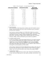
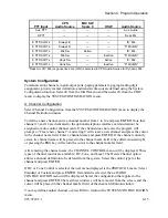
Auxiliary Input Port numbers 9-38 are assigned to the optional Expanded Aux. I/O
Card(s) (Part No. 702-9448) as follows: 9-14 to the first Aux. I/O Card, 15-20 to the
second Aux. I/O Card, etc. This allows the Model 4010 to support up to five Aux. I/O
Cards (30 ports).
Auxiliary Input Port numbers 1-8 are assigned to the Model 4010 main PC board
Spare/Aux. inputs (on connector P8) if these inputs have been configured as auxiliary
inputs. If the inputs have been defined as spare inputs instead (the default), Auxiliary
Input Port numbers 1-8 are unavailable and cannot be selected in this menu.
Auxiliary Output Port numbers 9-38 are assigned to the optional Expanded Aux. I/O
Card(s) in the same manner as the input ports as described above. Auxiliary Output
Port numbers 1-8 are assigned to the Model 4010 main PC board Spare/Aux. outputs
(on connector P7) if these outputs have been configured as auxiliary outputs. If the
outputs have been defined as spare outputs instead (the default), Auxiliary Output
Port numbers 1-8 are unavailable and cannot be selected in this menu. In this case,
however, three additional menu items will appear in the AUXILIARY
INPUT/OUTPUT menu to allow the spare outputs to be defined.
Note:
Auxiliary Output Ports 1 through 4 are logic level outputs. Auxiliary Output Ports
5 through 8 are relay closures. See Model 4010 Radio Dispatch Console Service
Manual (Part No. 025-9228) for pin-outs.
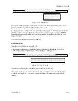
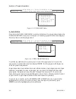
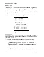
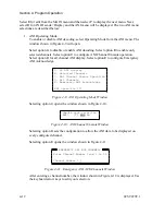
Selecting Auxiliary Input / Output Functions will display the AUXILIARY INPUT /
OUTPUT menu. From the menu you may assign an auxiliary input, one of three
different types of auxiliary outputs, or spare outputs.
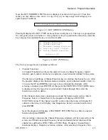
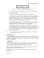
Selecting Auxiliary Input displays the INPUT PORT selection menu. Select a
previously defined input port by entering a number from 1 to 38 or using the
UP
and
DOWN
arrow keys to move through the defined input ports. After selecting an input
port, press
ENTER
. The next menu displayed allows you to select what type of input
this key will be and how the lamps will function on the key. If you select “C. Dual
Input”, the program displays a second INPUT PORT selection menu. Select the
second input port in the same manner as the first input port.
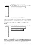
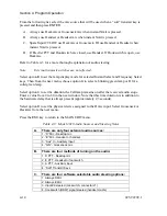
Selecting any of the three Auxiliary Output menu options displays the OUTPUT
PORT menu. Select a previously defined output by entering a number from 1 to 38 or
using the
UP
and
DOWN
arrow keys to move through the output ports. After selecting
an output port, press
ENTER
. The next menu displayed allows you to select what type
of output this key will indicate and how the lamps will function on the key. Selecting
output-only functions
A
and
B
completes the definition of the output key. Selecting
options
C
through
G
displays additional input port selection windows. Select the
additional input ports by entering a number from 1 to 38 or using the
UP
and
DOWN
arrow keys to move through the input ports. After selecting an input port, press
ENTER
.
Summary of Contents for 4010
Page 2: ......
Page 4: ......
Page 7: ...1 INTRODUCTION HARDWARE REQUIREMENTS 1 1 DEFINITIONS 1 1 MANUALS 1 2...
Page 8: ......
Page 12: ......
Page 16: ...Section 2 Installation 2 4 025 9229C 1...
Page 18: ......
Page 34: ...Section 3 Tutorial 3 16 025 9229C 1...
Page 36: ......
Page 58: ......
Page 60: ......
Page 62: ......
Page 64: ......
Page 108: ...Appendix D CPS Menu Structure D 44 025 9229C 1...
Page 110: ......


